|
|||||||


| Show your rotary car build up. Show off your Rotary Car build! |
|
|
Thread Tools | Display Modes |
|
|||||||
| Show your rotary car build up. Show off your Rotary Car build! |
|
|
Thread Tools | Display Modes |
 06-06-2011, 10:22 AM
|
#1 |
|
IT'S ALIVE!

Join Date: Dec 2009
Location: Richmond, VA
Posts: 811
Rep Power: 16  |
infernosg's S5 N/A Build
Several people already know about this but since I've starting making progress I guess it's time for a thread.
I have a '89 GXL that I've been using to get into road racing. I've owned it since June '09 and since then the only major modifications I've done have been to the suspension and drivetrain. Below are the two most recent pictures of the car I have (circa April '11):   This year was supposed to be my big HPDE year. Literally the weekend after those pictures were taken I overheated the car on the seventh session of the weekend. After that the car continuously pushed coolant into the overflow bottle so after 10 minutes of driving the low coolant buzzer would go off. It also got increasingly difficult to start over the next two weeks. The last few times it sounded like it was only firing up on one rotor although after applying some throttle it would sound normal. After that I decided to pull the engine:  The garage has been a mess from other projects around the house so I've only been able to expose the rear rotor as I don't have a large enough clean place to lay everything out. No obvious signs of a coolant seal failure yet:  Since I've pulled the engine I decided I might as well initiate all my long-term plans; no point in rebuilding the 6-port engine just to replace it in a few years. So since then I've removed A/C and P/S:  Gutted the emissions harness. That on the left is what remains and everything on the right has been removed: 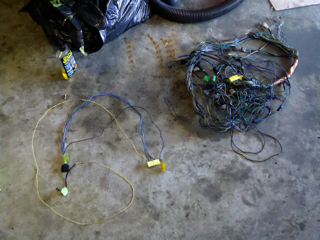 I will be running a Haltech Sprint RE so I am removing everything from the car not needed to legally drive it on the street. In addition to the EM harness I've also gutted the rear harness as I no longer have a need for AAS, the rear wiper, window cleaner, etc. Ultimately I want to do the same with what remains of the front and engine harnesses but I'm hesitating on removing the dash. The last time I messed with it plastic was breaking left and right. Shown below are all the wires and controllers I've removed so far:  Last week I received a set of S4 TII housings:  I've been thoroughly documenting my work so I have MANY more pictures but no one cares to see pictures of step-by-step wiring removal... If you haven't guessed by now I'm doing a 4-port N/A build. The block will be made of S4 TII intermediate housings, S5 N/A rotors, S5 N/A rotor housings with TII exhaust sleeves and RX-8 stationary gears, bearings and eccentric shaft. Intake will be a custom manifold with DCOE- or IDA-style individual throttle bodies. Fuel will be provided by two ID1000 injectors and four IGN-1A (Mecury Marine) coils will provide the spark. Exhaust will be comprised of a Defined Autoworks 4-port header and custom piping exiting at the rear driver's side. Everything will be controlled by a Haltech Sprint RE with a custom harness from LMS. Other items such as a rollbar and RT1000 racing seats will also be added along the way. I'd also love to replace the stock hood with a ligher fiberglass one and the rear hatch for a wiperless one. Feel free to comment/question and if you think you having anything that might be useful to me, suggestions or parts, let me know! |

|
| Bookmarks |
|
|


 Threaded Mode