|
|||||||


| RX-7 3rd Gen Specific (1993-2002) RX-7 1993-2002 Discussion including performance modifications and Technical Support Sections. |
 |
|
|
Thread Tools | Display Modes |
|
|||||||
| RX-7 3rd Gen Specific (1993-2002) RX-7 1993-2002 Discussion including performance modifications and Technical Support Sections. |
|
|
|
Thread Tools | Display Modes |
 08-27-2009, 06:00 PM
|
#1 |
|
Rotary Fanatic

Join Date: Mar 2008
Location: Brenham, TX
Posts: 335
Rep Power: 18  |
Greddy 4 bar map sensor with stock connector!
So I've been needing a 3 bar map sensor so I could start tuning for higher boost. Awhile back my Greddy Profec e-01 stopped working, and I thought.. I wonder if I can use the map sensor from the e-01 in place off my stock sensor? So I tried to find information on it and found very little except it's a 4 bar sensor, the part number is 16401301 and runs $116.
Originally I was just going to splice the harness and hook the wires up directly. (taking a guess at which wire goes where) Well when I went out to do some testing, I found that the connector on the map sensor will plug directly into the stock harness! I plugged it in and it registered 1v, but it wouldn't change with vacuum or pressure. Then I tested the stock harness' wires and It's: green/yellow = Signal Brown/White = 5V Black/Grey = Ground The orientation of the greddy harness (red,white,black) makes the black wire line up with the signal wire (G/Y), I figured this was the issue since black is usually ground. So I removed the pins, from the e-01 connector. It takes a little patience to figure out, but it's very doable (see below) Then I just switched the white and black pins around with each other. And it works now! Pressure/vacuum changes the voltage up and down as it should. In order to remove the connector pins from the greddy sensor, the yellow plastic piece inside the connector has to be pulled out from the front. I'm not sure the "proper" way to do this, I ended up getting out on accident by pushing a tiny screw driver(slightly larger then a large needle) through one of the holes on accident and it came out attached to the screwdriver. Once the yellow piece is out some small black retaining clips are revealed, I slid the small screwdriver behind them, then pushed with another screwdriver on the individual clips until they popped out the back of the connector. This only needs to be done to the black and white wires, switch them around and put the yellow connector back. Done. This would be a good alternative to the expensive apexi, or the GM w/ adapter harness, or for someone that wants to run huge amounts of boost. The correct scale and offset to use with the black datalogit box and universal software is Scale 9300 and offset 4500. I used a mityvac and a spreadsheet to get the correct scaling. Here's a pic of the sensor and the spreadsheet used to calculate the scale/offset. The stock curve is on there as well for comparison. 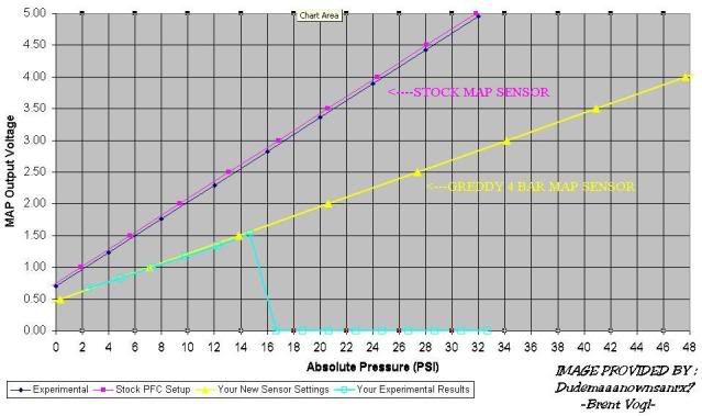 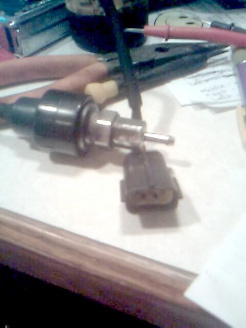
__________________
500+ HP thanks to:  Fast reacting IAT sensor thread! Mechanical Pre-turbo Water Injection Thread Dual Stock fuel pumps Thread T2 differential swap! |

|

|
|
08-27-2009, 06:38 PM
|
#2 |
|
Rotary Fanatic
Join Date: Mar 2008
Location: Brenham, TX
Posts: 335
Rep Power: 18 |
Here's a better pic showing the sensor plugged in to the stock connector.

__________________
500+ HP thanks to: Fast reacting IAT sensor thread! Mechanical Pre-turbo Water Injection Thread Dual Stock fuel pumps Thread T2 differential swap! |
|
|
|
|
| Bookmarks |
|
|
 Linear Mode

