|
|||||||


| Rotary Tech - General Rotary Engine related tech section.. Tech section for general Rotary Engine... This includes, building 12As, 13Bs, 20Bs, Renesis, etc... |
 |
|
|
Thread Tools | Display Modes |
|
|||||||
| Rotary Tech - General Rotary Engine related tech section.. Tech section for general Rotary Engine... This includes, building 12As, 13Bs, 20Bs, Renesis, etc... |
|
|
|
Thread Tools | Display Modes |
 04-04-2009, 02:33 PM
|
#1 |
|
Respecognize!

Join Date: Jul 2008
Location: Δx = ħ/2Δp
Posts: 3,190
Rep Power: 21  |
Megasquirt Info Thread
Alright so starting tonight or tomorrow im starting my Megasquirt wiring. Figured i would give out some general info as i work through it all. Might come in handy for some others. For starters, i am only using it for fueling, so some of the things i do would not apply if you wanted to have ignition control.
Below are two similiar wiring diagrams. One is specifically for the Rx7 running the CAS, the other is if you are planning on using the Dizzy. I am using the dizzy with a CDI box to make the signal usable. Now, if you are planning on using ignition control, you can not just use the "tach out" from the CDI as a signal for the megasquirt. But for fueling, it will work just fine. 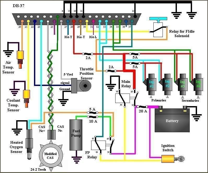 
__________________
For current updates and event coverage check out Follow on Twitter! @WhizbangRally Whizbang Rally's Webpage | Facebook |

|

|
|
04-04-2009, 02:36 PM
|
#2 |
|
Respecognize!
Join Date: Jul 2008
Location: Δx = ħ/2Δp
Posts: 3,190
Rep Power: 21 |
As far a sensors go, there are several ways you go about things. There is plenty of info on the megasquirt web forums related to sensors, but for the Rx7 almost everything is useable. The IAT (intake air temp) sensor will read off by 10 degrees. You can use a resister and figure it back to correct reading, but i just elected to drill and tap for using a GM sensor (which reads true). Mostly because i have an after market manifold and i have to drill and tap for it anyway.
The TPS, coolant temp sensor, etc will all work with the megasquirt.
__________________
For current updates and event coverage check out Follow on Twitter! @WhizbangRally Whizbang Rally's Webpage | Facebook |
|
|
|
|
04-04-2009, 10:21 PM
|
#3 |
|
The quest for more torque

Join Date: Sep 2008
Location: Sheboygan, Wisconsin
Posts: 855
Rep Power: 18 |
How about the stock MAP sensor, will it work? Are you using an S5 TPS?
__________________
1986 GXL ('87 4-port NA - Haltech E8, LS2 Coils. Defined Autoworks Headers, Dual 2.5" Exhaust (Dual Superflow, dBX mufflers) 1991 Coupe (KYB AGX Shocks, Eibach lowering springs, RB exhaust, Stock and Automatic) |
|
|
|
|
04-04-2009, 10:38 PM
|
#4 |
|
Rotary Fanatic

Join Date: Feb 2008
Location: Cleveland, Ohio
Posts: 159
Rep Power: 18 |
Mega squirts come with a 2bar map with most of the kits... i have mine with a 4bar... you can use a gm 3bar as well...
|
|
|
|
|
04-04-2009, 11:41 PM
|
#5 | |
|
Rotary Fanatic
Join Date: Sep 2008
Posts: 147
Rep Power: 18 |
Quote:
Also, it should be noted that the top wiring harness (for using the stock cas) requires internal mods to the Megasquirt to fire spark. It's also possible to build a second VR input sensor and use both inputs on the stock unmodified CAS. |
|
|
|
|
|
04-04-2009, 11:53 PM
|
#6 |
|
RCC Loves Me Not You

Join Date: Jul 2008
Location: Influx.
Posts: 2,113
Rep Power: 20 |
My question is however: how many inputs/outputs can you have max?
__________________
The Official FC Radiator Thread My Project Thread: Cerberus CCVT Virginia Rotary Group |
|
|
|
|
04-05-2009, 10:21 AM
|
#7 | |
|
Rotary Fanatic
Join Date: Sep 2008
Posts: 147
Rep Power: 18 |
Quote:
|
|
|
|
|
|
04-05-2009, 11:39 AM
|
#8 |
|
Rotary Fanatic
Join Date: Feb 2008
Posts: 157
Rep Power: 18 |
Does the CAS only need the Ne- & Ne+? What about the G- & G+?
|
|
|
|
|
04-05-2009, 04:20 PM
|
#9 | |
|
Rotary Fanatic
Join Date: Sep 2008
Posts: 147
Rep Power: 18 |
Quote:
The "better" solution is to build a second VR input circuit on the MS board, and use both wheels in the CAS without modification. Honestly, either way works just fine in most circumstances. |
|
|
|
|
|
04-05-2009, 10:52 PM
|
#10 |
|
Rotary Fanatic
Join Date: Feb 2008
Posts: 157
Rep Power: 18 |
Ok I bought an MS1 V2.2 and I'm having problem finding the right software and firmware. I tried the MT 2.25p3 and couln't get the COM to work on my laptop.
|
|
|
|
|
04-05-2009, 11:57 PM
|
#11 |
|
Respecognize!
Join Date: Jul 2008
Location: Δx = ħ/2Δp
Posts: 3,190
Rep Power: 21 |
im still confused on how to run the injectors. since it has two outs, would i have the injectors that are firing at the same time run one rotor at a lower pulse width?
__________________
For current updates and event coverage check out Follow on Twitter! @WhizbangRally Whizbang Rally's Webpage | Facebook |
|
|
|
|
04-06-2009, 08:36 AM
|
#12 | |
|
Rotary Fanatic
Join Date: Sep 2008
Posts: 147
Rep Power: 18 |
Quote:
|
|
|
|
|
|
04-06-2009, 08:49 AM
|
#13 | |
|
Rotary Fanatic
Join Date: Sep 2008
Posts: 147
Rep Power: 18 |
Quote:
The MS default is to pulse both injector drivers at the same time off the same map. On most non-rotary cars (or rotaries using the non-oem intake setup) where all the injectors are the same size, you can set it to alternate the two banks off of the same map. So for instance, if you were running an IDA throttle body like I was for a while, you would wire both of the outboard injectors to one driver, and both of the inboard injectors to the other, and run them in alternating mode. You can set it up with one driver per rotor, but you lose a hidden benefit. In alternating mode you are basically running the engine off of two injectors, but as the load increases the injectors will start to overlap; one bank is still firing when the next starts. Eventually at 200% (calculated) pulsewidth, both banks are firing all the time. This gives you a very good dynamic range, and makes it easier to idle on big injectors. Now the tricky part comes in when you have differently sized (staged) injectors, or when you have an intake setup with secondary throttle blades that don't open immediately (sound familiar? Both of these are true in various 13b configurations). At this point you have to run dual table. Wire the small/primary injectors to one bank, and the large/secondary injectors to the other. Then you have to map out both injector banks individually. One thing to note is that you can't put a zero into a VE table bin to stop the injector from firing at all (under most firmwares; check local listings). Instead, when you want an injector to not fire (ie, secondary injectors before the secondary throttle opens) put a "1" in the VE bin, and it'll put out -almost- no fuel. Close enough to get the job done, at least. |
|
|
|
|
|
04-06-2009, 09:25 AM
|
#14 |
|
Respecognize!
Join Date: Jul 2008
Location: Δx = ħ/2Δp
Posts: 3,190
Rep Power: 21 |
so i would then have one injector on each rotor firing at the same time?
__________________
For current updates and event coverage check out Follow on Twitter! @WhizbangRally Whizbang Rally's Webpage | Facebook |
|
|
|
|
04-06-2009, 05:10 PM
|
#15 | |
|
Rotary Fanatic
Join Date: Sep 2008
Posts: 147
Rep Power: 18 |
Quote:
|
|
|
|
|
|
| Bookmarks |
|
|

 Linear Mode

