|
|||||||


| Archives All the stickies in one place |
 |
|
|
Thread Tools | Display Modes |
|
|||||||
| Archives All the stickies in one place |
|
|
|
Thread Tools | Display Modes |
 06-02-2009, 01:36 PM
|
#1 |
|
RCC Loves Me Not You

Join Date: Jul 2008
Location: Influx.
Posts: 2,113
Rep Power: 20  |
The Rotary Car Clubs Official NA-to-Turbo How-to Ultimate Thread
Preface
The Object of this how-to is not to discourage or encourage the individual enthusiast from any and all modification to a vehicle such as the FC. In reality I would hope that a majority of individuals interested in doing any work with these cars be familiar with the very different aspects of the car and be able to feel comfortable enough to do radical engine, body, and frame alterations without worry. That being said however one must be cautious and fully understand the consequences of the actions they take. Please remember that I am no expert. Some of the information in this how-to may be partial to my own experience and since everyone already knows that I am no genius or anything more than a neophyte when it comes to these cars I would take everything in this write up with a grain of salt. Before attempting this sort of project be aware that you are going to be in for a "kick in the nuts" as it were, with what you think you know, what you know you don't know, and how much you still have to learn. If you do a search for many of the posts I've done before, you'll notice they're a lot of posts asking something specific regarding a project. Most of the time it was concerning this very project which I now write about. If you have questions I would highly suggest that you post it in the sister thread regarding this. This is purely for the how-to and amendments to the write up. Nothing other than clarifications and the like will be or should be posted here. As such, if you have a question regarding your specific project during this process feel free to post it outside this thread. There are many individuals who are much smarter than me that can probably answer your question better too. In any case, lets start this shin-dig.
__________________
The Official FC Radiator Thread My Project Thread: Cerberus CCVT Virginia Rotary Group Last edited by vex; 06-04-2009 at 07:16 PM. |

|

|
|
06-04-2009, 07:18 PM
|
#2 |
|
RCC Loves Me Not You
Join Date: Jul 2008
Location: Influx.
Posts: 2,113
Rep Power: 20 |
Table of contents:
Disclaimer Introduction Preliminaries InductionSize Your Turbo! Shopping For Your Parts Steps Step 1: Intake Step 2: Oil and Turbo Manifold Construction Step 3: Turbo Manifold Design and Construction Step 3.1: Turbo Manifold Mock Up and Planning
__________________
The Official FC Radiator Thread My Project Thread: Cerberus CCVT Virginia Rotary Group Last edited by vex; 04-22-2010 at 01:28 PM. |
|
|
|
|
06-04-2009, 07:19 PM
|
#3 |
|
RCC Loves Me Not You
Join Date: Jul 2008
Location: Influx.
Posts: 2,113
Rep Power: 20 |
Disclaimer:
Because our (being the country of my residence) has become so very litigious and individuals desiring a quick buck, I have included the following to avoid any confusion. In essence it states that you are responsible for everything you do, regardless of where you received the information. It is all on you.
In no way is this write-up or the site (including those who maintain or have contributed to this write-up/how-to and site/forum) on which it is hosted responsible for any damages and/or loss of life, limb, property, peace of mind, well being, monetary or otherwise, for which you incur during your build. This write-up/how-to is for informational purposes only and can only be thought of as such. The information contained herein is subject to update and alteration without notification to any and all concerned parties. Although every effort has been taken to ensure the information is accurate and easily available for confirmation no one has verified beyond their own personal experiences. As such, build at your own risk. Read all owners and operators manuals before beginning any portion of the project and be familiar with any and all tools used.
__________________
The Official FC Radiator Thread My Project Thread: Cerberus CCVT Virginia Rotary Group |
|
|
|
|
06-04-2009, 07:25 PM
|
#4 |
|
RCC Loves Me Not You
Join Date: Jul 2008
Location: Influx.
Posts: 2,113
Rep Power: 20 |
Introduction
Well, here it is. One of the most asked questions on any rotary forum: How can I get a turbo on to my NA RX7? Sure there are other derivatives of it, but for the most part it all comes back to wanting to turbo a Naturally Aspirated 13B. The long and short of it is that you really shouldnt put a turbo on an NA keg unless you want a few specific things and dont mind a few other things.
For instance you should know up front that simply turbo charging any naturally aspirating engine is no small feat. You have to plan out ahead of time what you want to do and how much youre willing to spend. If money is no object to you or you have amazing expertise or ability to fully custom mount a turbo than more power to you. As it stands however you may wish to consider the predominately easier and cheaper route of swapping in a similar series turbo version. That means swapping not only in the drivetrain (engine, transmission, differential, half shafts, drive shaft) but also the harness and ECU. Only desiring to have a hi-compression turbo charged engine eat up part of the full cost when compared to another project, IE: If given the choice between turbo charging an NA engine or swapping NA rotors into a turbo keg, you will be hard pressed to beat the price of just tearing the engine down and swapping in the rotorsall else being equal. If those are your only reasons for wanting to turbo charge the NA keg, I highly suggest you turn away now and not do it. You will be sorely disappointed and unable to re-coup your monetary loses which have been put into doing it. Keeping this in mind however, there are a few reasons to put a turbo on an NA engine. One of the rather large benefits of keeping the 13B 6PI engine and mounting a turbo to it is for the combined tuning possibilities of the 6PI on the S4 as well as the VDI on the S5. This adds another dimension to the possibilities of power and tuning, but more importantly provides additional ability for controlling the torque curve (and hence for this write up will focus predominately on the torque curve). Being able to modify the torque curve is the crux of this project. You will not see greater gains from the port size as you would from a similarly ported turbo engine, you will not see greater reliability from a similarly modified turbo engine. You will see more tune ability in the effective range of the 6PI and VDI. This means you will have the possibility of more low end grunt, and acceleration. This however can be compensated in other similar turbo charged engines by advanced tuning and correctly sized and plumbed turbo. If you have read the above and still desire to turbo your naturally aspirated engine be prepared to spend between $7,000.00 to upwards of over $10,000.00. This is of course assuming you purchase everything new. Only when you begin to receive parts that are significantly under retail does the proposition for turbo charging the 13B 6PI become monetarily feasible.
__________________
The Official FC Radiator Thread My Project Thread: Cerberus CCVT Virginia Rotary Group |
|
|
|
|
06-04-2009, 07:27 PM
|
#5 |
|
RCC Loves Me Not You
Join Date: Jul 2008
Location: Influx.
Posts: 2,113
Rep Power: 20 |
Preliminaries:
You’ve decided you’re going to turbo charge a 13B 6PI even after reading all that? So I guess that means I actually have to write something regarding doing some actual work. Before we even pick up and start ordering any parts for this project start by making a list. Make a list of all the things you’ll need to accomplish this project. The big groups to think about are:
1) Induction 2) Cooling 3) Oil 4) Exhaust 5) Fuel 6) Electronics This list will be broken out into individual sections and further discussion given to each individual component and what should be desired from each. With this simple 6 item list see what you can pick up for not too expensively, what will need to be custom fit, custom manufactured, or even pieced together. Seeing what you have before and what you still need for the build will help you reduce some of your associated costs. To make things develop a spreadsheet that can be used to organize the individual parts, their associated costs (including shipping), and location to order from. Also before endeavoring to accomplish this project please remember that this is a very time consuming build. Do not plan on having the car down for just a weekend. This will require you to make some arrangements to ensure you have adequate space to tear down and build the car. Set aside additional time if you plan on rebuilding and porting the engine as well as additional time if any work is needed on the engine bay such as paint. Once that is accomplished pressure test your engine prior to removing anything from the car. Ensure you have adequate compression and the seal conditions appear to be good. Validate your numbers using a rotary specific compression tester which can be done at any Mazda Dealership. Do not buy the compression tester, but have them test your compression and give you a copy of the numbers. Any discrepancy in the compression of the engine should be dealt with prior to beginning the project. If you find you have low compression or a stuck seal. Attempt to remedy the problem without breaking apart the engine and check the compression once more. If all seals appear to be in functioning condition and you are able to validate all concerns with the engines condition by direct visual confirmation (mirror or flexible bore scope in the spark plugs and exhaust and intake ports) that the engine is indeed in working condition, proceed with the build. Be aware that if there is any damage to the housings or seals turboing the engine will only exacerbate the problem. Ensure that your working location is free of clutter and debris that will cause considerable headache during tear down and build. Organizing and marking parts during tear down will greatly increase your speed on assembly and thereby decrease your time of the build. It costs a little upfront but has very nice returns.
__________________
The Official FC Radiator Thread My Project Thread: Cerberus CCVT Virginia Rotary Group Last edited by vex; 06-09-2009 at 11:03 PM. |
|
|
|
|
06-04-2009, 07:28 PM
|
#6 |
|
RCC Loves Me Not You
Join Date: Jul 2008
Location: Influx.
Posts: 2,113
Rep Power: 20 |
Induction
As was previously mentioned you will need to further construct this portion of the list. Since this deals only with induction you need only concern yourself with the physical objects which will cause pressurized air to enter the combustion chamber. A simple list may be:
1) Turbo 2) Intercooler 3) Intercooler Piping 4) Silicon Couplings 5) Silicon Line 6) Air Filter 7) Adapter 8) Blow off valve 9) Gaskets 10) T-Bolt clamps When selecting the Turbo you will need to decide what your goals are. You can easily pick up a stock turbo and have it rebuilt and sent off to become a hybrid and there by increase its efficiency. Doing this however will completely depend on your end goals and price range. An alternate would be to pick up a universal type turbo charger, for instance Garrett or Turbonetics. They produce a wide range of individual turbos for most applications and can be easily applied to this style of build. Be aware that 13B engines are extremely efficient when it comes to ability to run relatively large turbos and have them spool quite quickly. Ensure that the turbo you do select will supply enough air at high RPM and will be able to spool fairly quickly. When you have made your choice begin the look for your intercooler. In my own personal application I went through two turbos. One was an S4 stock turbo which appeared to have little to no shaft play. The trouble was when I broke apart the turbine housing I noticed stress fractures and the turbo itself was rather hard to turn. I opted instead to purchase a Turbonetics T60-1 turbo and was able to secure it for well under retail. Word of warning for using an off the shelf turbo: You will need to construct or pay some one to construct a turbo manifold for use. All manifolds I have seen will not work with the 6PI and as such will defeat the purpose of turbo charging a naturally aspirated engine. An intercooler should be chosen by the turbo you have selected. If the turbo becomes inefficient at the revolutions you play to stay in it may be worth your wile to select an efficient intercooler to reduce the charge air temperature as much as possible. Efficiency of intercoolers is directly related to the surface area that sees temperature different air. If you have 90*F charged air going through the intercooler on a day that has 90*F ambient air, your air intake will not lose any temperature until you begin to move air through it. Reducing the charge temperature greatly reduces the probability of pre-ignition or reaching the spontaneous flash point of the fuel. As for piping, choosing aluminum piping is a standard, but what is not a standard is the diameter which the piping is. Usually 2.5 is used for most charge piping. However, based upon your turbo and your intercooler inlet/outlet you may wish to select a smaller or bigger diameter pipe. Transitions can be used, but may not be the best option available, or desired. Keeping the charge piping consistent with the intercooler and turbo size reduces side affects the with ideal gas law. P=nRVT (R is Plancks constant and n is number of moles) can be re-arranged in such a way as to say that P/(nRV)=T which means that as the Pressure and Volume of the charge piping directly affect the Temperature of the charge air. So if you have a constant pressure through out the system and since the volume isnt dynamically changing, your temperature is going to be constant. Now if we have a nominally large volume the temperature will be less than compared to a nominally small volume. Which means, the bigger the pipe the better (beware though that the bigger your pipe the longer your turbo will take to pressurize the piping, which equates to lag). There are other possibilities for piping such as Carbon Fiber Reinforced Plastic (CFRP) or Fiber Glass Reinforced Plastic (FGRP) Both have their benefits and insufficiencies, though depending on your budget might be well worth your money and time. Silicon couplings can be reduced if you have the money and time to send out a specific set of pipes out to be copied for a mandrel bent piece and shipped back to you. Doing this ensures smooth transitions in corners and ergo faster intake velocities with less turbulence (I will not address turbulent flow compared to laminar flow here). It also reduces the possibility of popping a coupling and developing a boost leak. For those of us that do not have the money to get mandrel bent aluminum charge piping we must make do with silicon couplings or high heat resistant rubber couplings to connect the universal charge piping together. These can be found for different amounts online so look around and see what you can find. Silicon line will be necessary to hook up a lot if not all the sensors and other goodies youll need to run a turbo on your 13B 6PI. Silicon has a few advantages over rubber, but they will not be discussed in depth in this write-up. Suffice it to say that silicon will withstand more direct and indirect heat with less hardening and deterioration then when compared to normal rubber lines. That being said there is a rather large price difference in Silicon line and Rubber line. But in this case you get what you pay for. The remaining portions of the list depend completely on how you do the build, what ems you will use, retention of the AFM, and other key features. If you know what youre going to run already then go ahead and skip ahead. However if you do not, be aware that depending on what engine management you run you will have to appropriate additional funds to things such as an AFM adapter plate to fit a high flow filter, or fit additional intake piping to route the cone filter away from heat, etc. About the only thing that will not depend on your ems selection would be the blow off valve and the T-Bolt clamps. Assuming that the T-Bolt clamps to be self explanatory Ill move on to the blow-off valve. Blow-off valves are simple pressure release valves and are installed to relieve compressor surge when the throttle body suddenly closes after being at WOT. There is some argument concerning BOVs and their actual functionality, however compressor surge and resultant cavitations is indeed destructive and will need to be carefully considered if you chose not to use a BOV.
__________________
The Official FC Radiator Thread My Project Thread: Cerberus CCVT Virginia Rotary Group |
|
|
|
|
06-09-2009, 09:39 PM
|
#7 |
|
RCC Loves Me Not You
Join Date: Jul 2008
Location: Influx.
Posts: 2,113
Rep Power: 20 |
Cooling
Do I really need to say anything about this? We all know or at least should know that our engines in any form; whether 13B 6PI or 13B Turbo, et al, produce a massive amount of heat for their size. Our nominal temperatures are between 170̊-220̊ F and we start to run hot at 230̊ F. Anything greater than 230̊ F you run the serious risk of destroying an engine—though there have been instances where individuals have seen engines at 250̊ F, but there again it was during a race. If you’re seeing temperatures that hot, then there’s something seriously wrong with your cooling system and is in drastic need for overhaul. As such there is already a thread made concerning picking and choosing a new radiator. Use it and select one that fits your needs.
However if you’re turbocharging your 13B 6PI one needs to take a few things into account prior to constructing the list: 1) Heat normally produced by the engine 2) Heat produced from the turbo 3) Heat produced by the close proximity of the exhaust against the engine 4) Shielding 5) Alterations to coolant flow 6) Coolant composition 7) Expansion Rate 8) Coolant pressure and a host of others. With these things in mind please consider the parts list below. You may need all the parts listed, you may not. That is a decision only you can make when you sit down and think about it. Something else to consider is what is termed in engineering circles as factors of safety. Basically when engineers sit down to design something where individuals will use it on a regular basis they start by figuring out the bare minimum of what they’ll need to do to accomplish a specific task. Once that criteria is set they start to crunch the numbers, and in their number crunching they start to bring in factors of safety: Instead of making a pressure vessel able to withstand 1000psi they make it able to withstand 3000psi. Instead of making a fuel system that is capable of only producing 40psi at 90 g/h they crunch the numbers so they can build one that produces 40psi at 180g/h. The same thing we can apply to our cooling. Let’s take a worst case scenario: We plan on running a fresh NA engine with a monster of a turbo. Previous to this we knew that our engine would run hot, seeing temperatures upwards of 220̊-230̊ F. We then assume that the turbo will add an additional 20̊-40̊ F to the overall temperature of the coolant. We also know that the turbo will add another 40̊-90̊ F to the ambient air temperatures that our AFM and throttle body will see. That being the case, we need to select a sufficiently good radiator to reject the massive increase in heat, yet lets also include a factor of safety of about 2 to 3. So instead of choosing a radiator that can reject 270̊ F we choose one that can reject 500̊ F. As so, let’s begin with a parts list. 1) Radiator 2) Brackets 3) Adapter 4) Coolant Lines for the turbo 5) Adapters for the coolant lines to the turbo 6) Fan 7) Thermostat 8) Relay When selecting a radiator look for a radiator that can handle the temperatures we’re adding to the engine. An all aluminum racing radiator will handle the temperature increase just fine. The problem comes in them not normally being a simple drop in fit. You’ll need to alter the mounting locations or the actual mounting location on the car. For a more detailed write up concerning selecting radiators see this link. Depending on your radiator selection you’ll need to either find an adapter (which is harder than selecting your radiator) or fabricate one yourself. You may need to go from 1.5 inches to 1.75 inches or some other measurement that matches what you need to connect to the water pump housing (or ignore this if you go with an electric water pump). If you go with turbonetics inc off the shelf turbo they sell a “universal” water line kit. They’re stainless steel lines and hook into the heater core lines and attach with a -4AN line and connect to the turbo with some banjo bolts. Now be careful because they sell two versions. One is “short” and one is “long”. Go with the short if you can. I went with a long version and they’re a little too long for my liking. This does not mean that you can’t get your own made. Pick up some -4AN stainless steel hose (1/4in) and some fittings and go to town. You can do banjo bolts do it. They provide a much more compact installation and allow a much cleaner install. Fans usually get hashed out every other day on these forums so just make sure to pick up a fan that can pull enough CFM (2500+) to cool the engine when not moving. Also consider ducting and ensuring that all the air can be pulled towards the radiator. If not, at least attempt to have enough air hit the radiator as possible. With a fan you need to run it off a thermostat or off a standalone (discussed later). “Well, why not run it off a switch and I’ll just flip it when I get in the car?” It seems like a non-argument no? Think about it though. Are you willing to risk a rebuild because you forgot to flip a $5 switch when you first sat in the car? Why not spend an extra $35 and never have to really worry about flipping a switch again? You won’t run the risk of losing your engine because you were forgetful, you won’t run the risk of frying some wiring because there’s too many amps being pushed through it. Just get a thermostat, an adjustable one if you really, really want to. You can even pick up really nice thermostats that can run the fan even after shut down so you car can cycle even more heat. So, don’t risk it. Get a thermostat. Whether it’s a push in probe type that you stick in your radiator or a water npt threaded type, it doesn’t really matter—though the npt threaded type is better and less chance of a hick up. Now with a thermostat you can also get one that has a built in relay which draws power directly from a switched source. If your thermostat does not, pick one up. It helps elevate extra current from wires that aren’t able to support the amperage.
__________________
The Official FC Radiator Thread My Project Thread: Cerberus CCVT Virginia Rotary Group Last edited by vex; 06-09-2009 at 09:41 PM. |
|
|
|
|
07-11-2009, 06:38 PM
|
#8 |
|
RCC Loves Me Not You
Join Date: Jul 2008
Location: Influx.
Posts: 2,113
Rep Power: 20 |
Oil System
Sorry about the delay. It's been a little hectic lately so I'm just now having some spare time to sit down and write this while my shoulder heals up.
We've covered a lot so far... and I know; not a lot of pictures have been shown so far. Don't worry they're in the pipe line. I just want to maximize the information up front so there's no delusions of what you may be attempting. This portion however is perhaps the most important for our engines. If you haven't already, check out this thread as it will give you a basic understanding of what oil you should be using, why you should be using it, and results of other oils that have been used. Make sure you read it. It's important. Do not read any further until you have finished that thread (It's only a couple pages at the most). Alright. You read it right? Good. Now that you have a fundamental understanding of what you're going to be pouring into your engine to lubricate your bearings, cooling your rotors, lubricating your turbo, and what you'll more than likely be spilling/leaking on the ground at some point or another--you're ready to figure out what you need for your oil system. The oil system is pretty straight forward, but there's a lot of little things you may miss if you don't really pay attention. I'm still figuring out the little details on my system so don't be upset if you have a few little bugs to work out. The important thing is that you get oil where it needs to be when it needs to be there. You also need to ensure that the oil is going go arrive at it's intended destination under the proper pressure. There's no sense in having really great oil that can not get to where it needs to be, ya dig? With that in mind a simple, but detailed list is as follows. Remember, this may be more or (probably more likely) less than you need. Alter the list as you see fit to better work with what you have on hand, and what you can easily acquire.
Not a bad list, but definitely longer than most. I'm not going to go over them specifically in detail, but will explain a few of the more... not-so-obvious ones. First off the Oil Pressure Regulator(OPR). It's located in the oil pan connected to the rear housing (only if my memory serves me correctly. It may not be). Basically you will need to up the pressure to ensure that adequate oil is maintained throughout the system. This also means you'll need to ensure that you're not upping it too much and rupturing oil lines. It could prove very bad if that were to occur. Very bad indeed. Now you can spend the dime on getting an adjustable OPR or you can modify your existing one to see the appropriate pressure. If you wish to do the latter, look up the video from Pineapple Racing where they modify their stock OPR to function at a higher pressure. There are other ways to do it, but I found that way the easiest. The rest should be fairly straight forward. Make sure the oil stays cool so you must have a way to ensure that the oil gets to the proper location reliably. In my setup I chose to do away with the stock lines and manufacture my own since I was planning on moving my Oil Cooler forward and make it perpendicular. The lines themselves are quite easy to make, and if you have any -10AN or larger you may be able to make them for under $70. I actually went out and bought what I needed to make them from a local individual and was able to construct them myself for only $70. It's not a bad deal, especially when you consider that other shops will ship you lines that may not function as well as you would like them and for about 3 times the price of what I constructed mine for. But that's neither here nor there. So moving on. The oil filter adapter is needed to draw oil pressure from the engine and put it on the turbo itself. The turbo's oiling system does not draw it or relinquish it under it's own power. For that cause we need an oil feed line and an oil drain line. Each dealing with the same subject but from two different aspects. The oil feed line allows oil under pressure to be fed into the turbo. This usually is a -4AN or smaller line that connects up to it. Remember your application may be different and require different things. If you have a Turbonetics inc turbo you do not need an oil restrictor unless you see over a specific PSI of oil pressure at WOT. You'll need to talk to your turbo manufacturer to ensure you have one if needed. The oil return line needs to be mounted in such a way as to ensure that it's a direct (read that up/down) path to the oil as possible. If that is not possible in your application you'll need to pick up a scavenge pump. I on the other hand have had some success in draining the oil below the oil line in the oil pan, but that is through the use of pipes, an oil accumulation chamber and a soft line to the welded bung. It works well, but I may eventually trade over to a scavenge system at some point for a cleaner install and less troubles. There are still other things to make sure you have taken care of, but this should help you get on the right track. Make sure you understand these basics before going forward and laying down hard earned money for part you don't need or want.
__________________
The Official FC Radiator Thread My Project Thread: Cerberus CCVT Virginia Rotary Group Last edited by vex; 07-11-2009 at 07:04 PM. |
|
|
|
|
07-12-2009, 02:32 PM
|
#9 |
|
RCC Loves Me Not You
Join Date: Jul 2008
Location: Influx.
Posts: 2,113
Rep Power: 20 |
Fuel
With more air you need more fuel, otherwise as you might already have guessed; the engine will run lean and possibly have a catastrophic detonation event. This is when you need to make sure you have the proper electronic suite to ensure proper monitoring of your system. Never push your setup beyond what it can handle. With that however you can ensure a long engine life and plenty of room to grow by employing and using the following:
That's about all you need. Now remember, you need to ensure you have enough fuel for the amount of pressure your new intake system will produce. Do not under bid on the fuel. I currently run a rising rate FPR and it's able to maintain if not exceed my needs to feed 550cc/min and 720cc/min injectors. Realize that both a 550cc/min primary and secondary injectors is the bare minimum you will need to run stock levels of boost pressure or below. If you run any smaller you run the very likely risk of maxing out the injectors and running lean. Additional information can be found online about running injectors at max peak and hold for extended period of times. Now there are alternate ways to net additional fuel, but they are more complicated than not and would probably be better suited for another discussion altogether. As for fuel pump you can go with which ever one you feel will flow enough at the correct pressure. I currently am running an FD fuel pump as it's a direct replacement with little hassle at all to install. Others have installed Walboro's, Aeromotive, et al and have had success running those. Conversion over to a Parallel fuel setup enables you to narrow down potential fuel problems. It also ensures that regardless of injector problems you will not have a problem that will cut fuel off to all fuel rails. (this of course is an extreme case: where one rail becomes clogged and unable to function--it may cost you an engine if it happens at the wrong time, but it's more likely that you'll spot the problem and be able to correct it without losing an engine) You can check out Ted's site about conversion. It's not hard to do at all. While your messing with the system you may as well replace the fuel filter to ensure that you're pumping nice clean fuel into your engine. Just sayin'
__________________
The Official FC Radiator Thread My Project Thread: Cerberus CCVT Virginia Rotary Group |
|
|
|
|
07-12-2009, 02:44 PM
|
#10 |
|
RCC Loves Me Not You
Join Date: Jul 2008
Location: Influx.
Posts: 2,113
Rep Power: 20 |
Exhaust
Exhaust is one of those things that gets hashed out every other day on forums so I'm not going to detail it all that much. But here are a few things to consider:
When doing this project you need to figure out up front what's going to be more cost effective or worth your time. If you are doing an off the shelf turbo manifold you may be able to secure an off the shelf exhaust system. I would highly recommend spending the extra money and going that way if you can. Remember though if you are planning on keeping the 6PI you'll need to manufacture your own turbo manifold. This means no off the shelf exhaust system will work for you. Which means you'll have to spend extra time to hunt down materials and find persons or tools that will enable you to accomplish what you need done. By this same token you can hybridize the two. If you do construct your own turbo manifold you can easily construct a down pipe that can connect to a custom mid pipe. This mid-pipe will then need to connect to an off the shelf cat-back system. This will probably provide you with the least amount of headaches... and may be a route I eventually choose to go with. As it stands however I found it significantly cheaper to manufacture the exhaust myself buying off the shelf universal components. Stores like Racing beat and summit-racing are indispensable when doing the exhaust that way. If you choose to build your own you will need to figure out exhaust sizes for your HP/Trq Goals, and locate a dealer that can supply you with the proper materials. Mandrel bending will flow much better than crush tube bending and may prove to be the exactly what you need. I recommend the vendors on here as they are very helpful and more than likely have the parts or materials you will need. Of consequence if you choose to manufacture your own Turbo Manifold you will need to plan it out before you weld all the pieces together. I was lucky and had access to CAD software and built a digital model of mine prior to even making the first welds. On top of that, I was able to test fit prior to each individual part of the manifold in that I saw that my original blue prints could not function how I wanted them too. The off the paper revision caused me to move the wastegate runner to the underside of the manifold rather than on the top. As it stands it functions rather well without much issue. Further details on constructing your own manifold will be presented later.
__________________
The Official FC Radiator Thread My Project Thread: Cerberus CCVT Virginia Rotary Group |
|
|
|
|
07-12-2009, 03:02 PM
|
#11 |
|
RCC Loves Me Not You
Join Date: Jul 2008
Location: Influx.
Posts: 2,113
Rep Power: 20 |
Electronics
TitaniumTT will absolutely bite my head off if I didn't include this section, and for good reason. The electronic suite you choose to run in your car is your line of defense from potential problems that may cause you tremendous grief and pain with regard to the engine. What you choose to monitor should be the key index's that measure the condition of the engine. Unfortunately we have nothing that directly measures the condition of the engine at any given operating scheme. What we can do however is monitor specific subsystems for their function and secure base line readings of all systems throughout the nominal operating conditions and then compare those readings throughout any situation that may arise.
What we have been discussing so far are all the subsystems we need to monitor. Oil, fuel, coolant, etc. They're all the portions of the engine that we need to ensure we can have data from if we need to. It will do us little good to know that we are low on coolant when we don't know what final temperature we were able to keep the engine at while we attempted saving the engine. It would do us little good to know we are low on oil without knowing that the pressure is good but the temperature is out of spec. These systems however do not need to be monitored all at once, nor do they need to be monitored in real time under most situations. For this cause, you as the builder, need to figure out which specific systems to have dedicated to real-time gauges, and which systems need only access to be datalogged. The systems I chose were: AFR's (Exhaust), EGT (Exhaust), Boost/Vacuum (Induction), Oil Pressure (Oil), Coolant Temperature (Cooling). Those provide me with enough information to know if my engine is operating under satisfactory condition. Stock gauges themselves are helpful, but they lack a specific degree of accuracy you might want, if so consider altering your setup and real estate for more gauges. Another portion that needs to be addressed within this section is the ECU/EMS. The stock NA ECU will not cut it--and sadly neither will the RTek 2.1 system for the NA-Turbo. An alternate way would be to secure a Turbo ECU and Harness and have it modified for the RTek 2.1. It then should have no trouble running what needs to be run. This however has not been tested by me and so I can not verify it. The other option is to go piggy back. You however lose control to alter spark, but that may not be necessary depending on the boost level pressure you plan on running. You may also need to replace the MAP sensor with one more capable to handle positive pressure. The NA MAP sensor only is able to read up to 2.4PSI (I have rarely seen it read above 4PSI even though I have seen as high as 8PSI on my gauge--don't ask). The final option is to go with an aftermarket EMS. I personally plan on going this route and have had many discussions with members on this and other forums to ensure my understanding of what each individual EMS brings to the table. Some top contenders in my book are MoTec, MegaSquirt, and Haltech. This is not to discount other EMS boxes such as MicroTech, Wolf3D, and others--but to show my specific inclination based on past conversations. What the biggest thing you should consider is what you plan on running and how you plan on running it. If you need specific functions or are only able to run specific devices with the use of a specific ECU you may wish to hunt around to see what one can do the job. This and of itself could be it's own write up, and maybe some one will one time in the future. But this is just to give you a basic understanding. So we'll go over a little more detail later on in the write up.
__________________
The Official FC Radiator Thread My Project Thread: Cerberus CCVT Virginia Rotary Group |
|
|
|
|
08-22-2009, 02:26 PM
|
#12 |
|
RCC Loves Me Not You
Join Date: Jul 2008
Location: Influx.
Posts: 2,113
Rep Power: 20 |
A little bit about choosing a turbo
Here's some helpful information about what Turbo you want to run. Bigger is not always better. This information is taken from the Turbonetics inc Website located here. I didn't write these things and as such all credit is given to Turbonetics Inc and deals simply with their line of turbos.
Once you have chosen your goals you now know what you need to do. So lets begin this process of turbo charging your NA. I will be using pictures from my build a T60-1 mated to a 6PI or as some refer it to a GXL-T.
__________________
The Official FC Radiator Thread My Project Thread: Cerberus CCVT Virginia Rotary Group |
|
|
|
|
11-09-2009, 01:33 PM
|
#13 |
|
RCC Loves Me Not You
Join Date: Jul 2008
Location: Influx.
Posts: 2,113
Rep Power: 20 |
Shopping
Alright, here we go. You've read the preliminaries (hopefully), and you've made a detailed shopping list of everything you want to install in/on your car. Consequently you're wondering where you'll be able to pick up everything you need for this conversion. Unfortunately you'll have to shop around. I would suggest that you check the vendors here as they offer some of the best prices around.
Consequently you'll be eating up most of your money in the EMS and the Turbo. The rest of the money will be divided up in the incidentals and welding/fab work that will be done. It's now time to start buying your parts. Buy the big parts on your list and be prepared for buying a little extra here and there (AN fittings, adapters, steel, aluminum, etc). Also shop around. Most times you can save a couple bucks if you can stand to wait around for delivery.
__________________
The Official FC Radiator Thread My Project Thread: Cerberus CCVT Virginia Rotary Group |
|
|
|
|
11-09-2009, 01:45 PM
|
#14 |
|
RCC Loves Me Not You
Join Date: Jul 2008
Location: Influx.
Posts: 2,113
Rep Power: 20 |
Step One: Intake
Starting with a regular old engine bay:
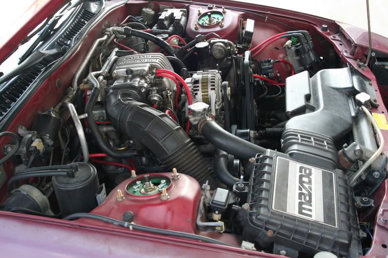 You'll need to start breaking out the different parts of the engine bay that you wont need anymore. Such as your snorkle, your air filter box, and a few other things here and there. Next you'll want to remove your manifolds (both the exhaust and intake). This would also be a good time to rebuild the engine (It's what I did). Next we'll focus on creating more room for the turbo by shaving portions of the lower intake manifold: 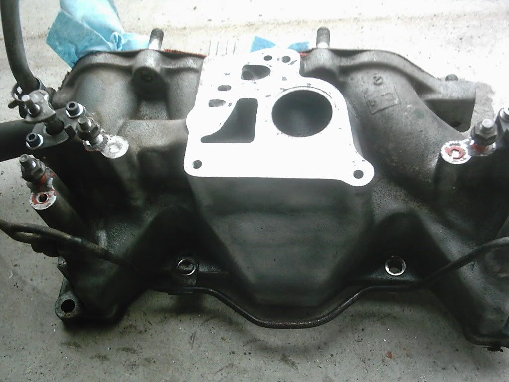 Then take an aluminum die grinder tool and remove material a little bit at a time 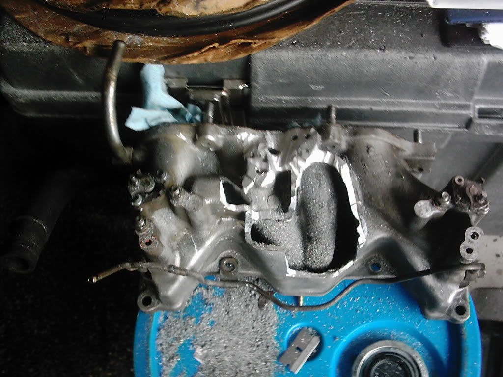 You want to maintain the integrity of the intake cavities, while removing the parts and cavities connected to the valve. This frees up a lot of space and should end up looking something like this: 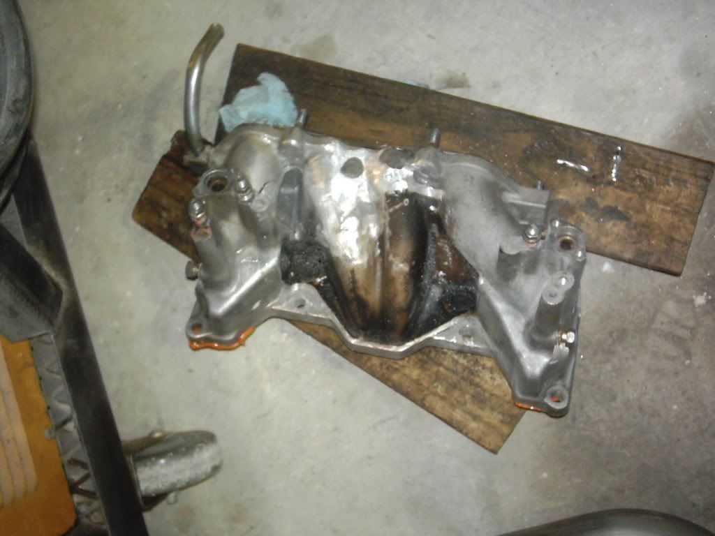 This will allow for mounting the turbo higher than the oil pan, and eventually a better--more condensed assembly. You also see that large grey dot? That's high temperature metal epoxy. It's there to fill a tap hole that is there for the pressure sensor. You'll need to fill it. Either braze in some aluminum filler, tig weld it (if you're brave enough), or just through some epoxy on it. At this time you may also want to port the throttle body. But I will not cover it in detail here--there's other threads for that. 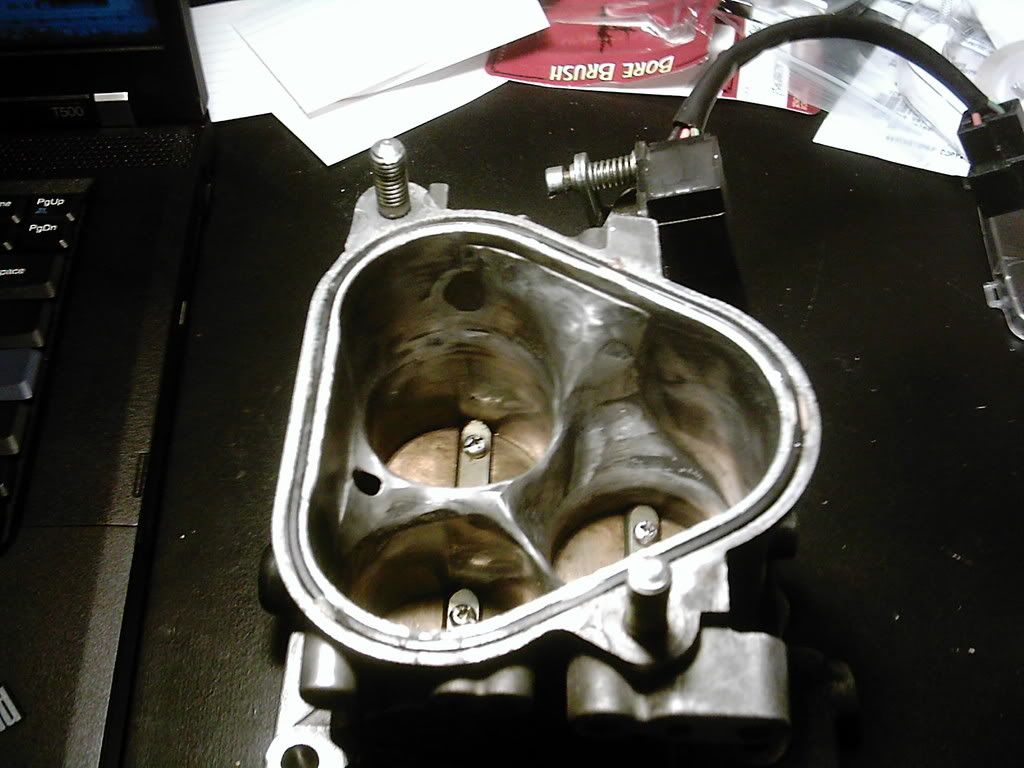
__________________
The Official FC Radiator Thread My Project Thread: Cerberus CCVT Virginia Rotary Group |
|
|
|
|
12-30-2009, 07:56 PM
|
#15 |
|
RCC Loves Me Not You
Join Date: Jul 2008
Location: Influx.
Posts: 2,113
Rep Power: 20 |
Now that you've "gutted" your engine bay you have room to work. (I'm assuming you've already rebuilt your engine, and ported it for whatever you want and have re-installed it).
I adjusted the location of the oil cooler and made new oil cooler lines so allow more direct cooling of the oil and free up space towards the front of the engine bay (this is not necessary, but may be something to think about) 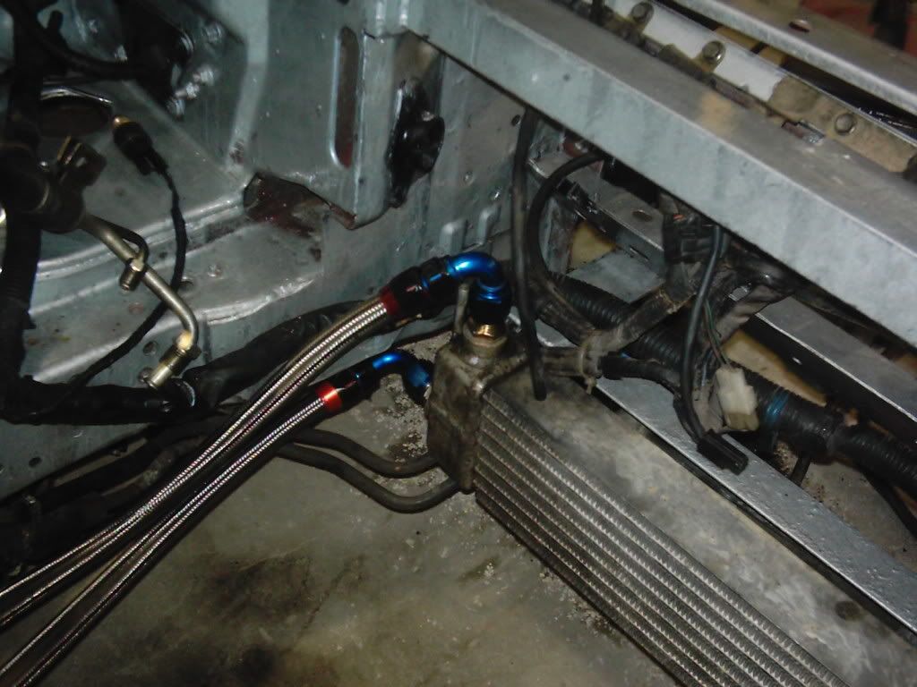 Oil cooler lines 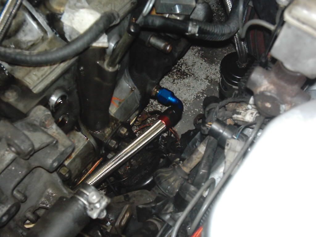 New Oil Cooler Location 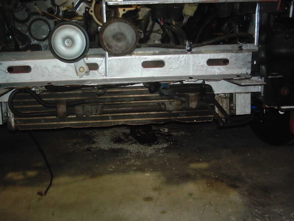 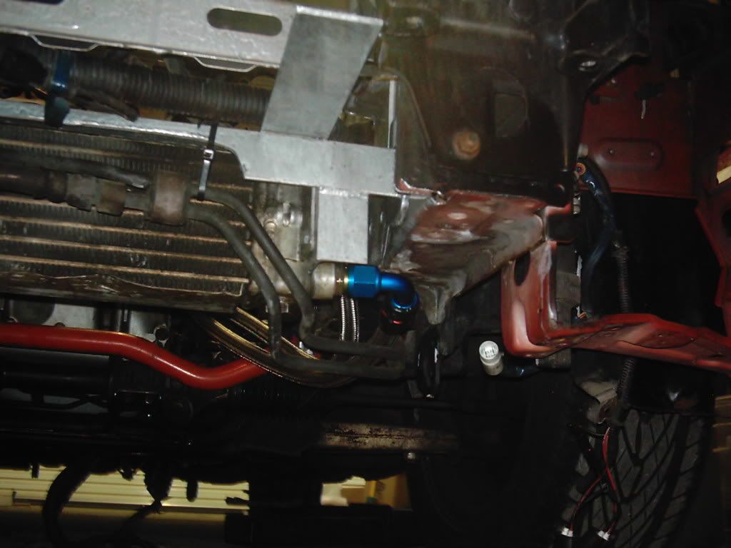 By this time I imagine you've also selected and bought your turbo: 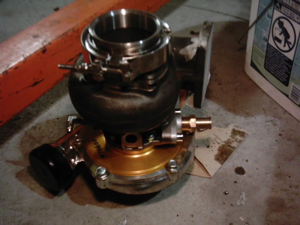 The use of adapters I have fitted my 60-1 turbo with a v-band connection. I highly recommend V-bands as they are extremely easy if you ever need to do anything with the turbo. Next you'll need to mount the upper intake with the actuators (if you're going to keep them), and find the ideal spot to mount the turbo. Here is a mock-up of what I intended to do: 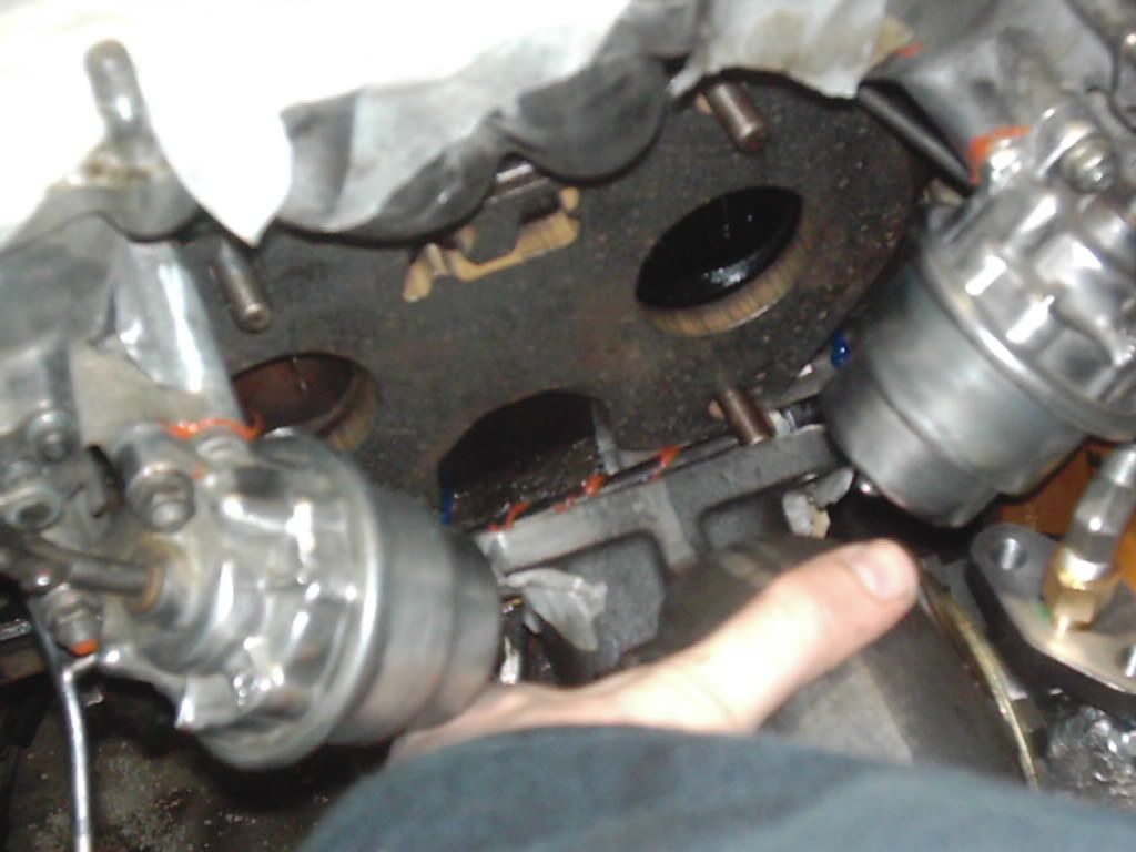
__________________
The Official FC Radiator Thread My Project Thread: Cerberus CCVT Virginia Rotary Group Last edited by vex; 04-16-2010 at 11:23 PM. |
|
|
|
|
| Bookmarks |
|
|
 Linear Mode

