|
|||||||


| Show your rotary car build up. Show off your Rotary Car build! |
 |
|
|
Thread Tools | Display Modes |
|
|||||||
| Show your rotary car build up. Show off your Rotary Car build! |
|
|
|
Thread Tools | Display Modes |
 05-22-2012, 06:32 AM
|
#31 |
|
Rotary Fan in Training
Join Date: Mar 2008
Posts: 86
Rep Power: 18  |
Looking good!
Sometimes I kick my self for not going this route, rather then a full turbo conversion 
|

|
|
05-22-2012, 10:49 AM
|
#32 | |||
|
IT'S ALIVE!

Join Date: Dec 2009
Location: Richmond, VA
Posts: 811
Rep Power: 16 |
Quote:
Quote:
Quote:
|
|||
|
|
|
05-30-2012, 08:06 AM
|
#33 |
|
IT'S ALIVE!
Join Date: Dec 2009
Location: Richmond, VA
Posts: 811
Rep Power: 16 |
I was looking into alternator relocation kits to solve my interference issues last weel. I ended up going with the Xtreme Rotaries alternator relocation kit. I received this exactly one week after I placed the order. Not bad for shipping from Australia to Ohio. Here it is all unpackaged:
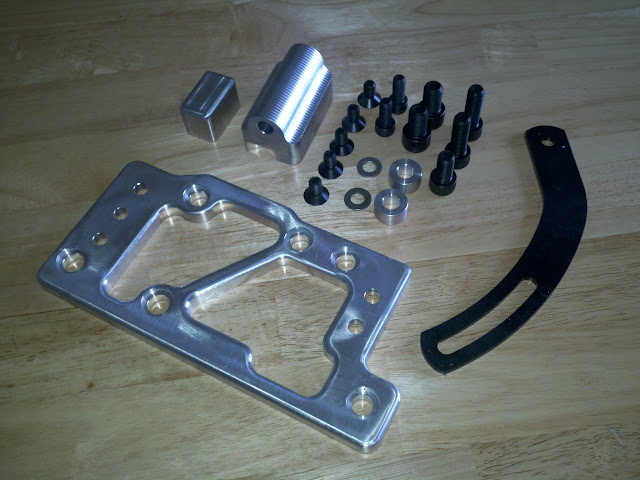 I'm pleased with the quality of the kit. 100% milled and polished aluminum and all bolt holes are counterbored/countersunk. I went with this kit due to the OEM-style tensioning system. All the other kits I saw used heim joints. In hindsight I could have made somehting like this myself but it wouldn't have been aluminum and it wouldn't be as nice. Installation was straightforward and I think I had more difficulty removing the studs from the front cover and front iron than setting up the alternator. Installed in the car: 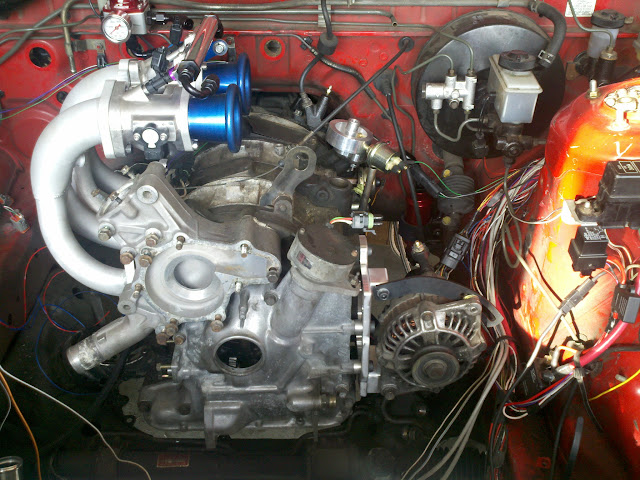 It looks tight between the engine and the frame rail but even at both extremes of the tensioning range there is clearance. The only issue I ran into was with the tension arm. With the alternator installed the tension arm is about .25" away from the alternator mounting point. The stock tension arm has a couple bends in it where the arm included with the kit does not. This was easily fixed with a few washers. The only concern I have is how close the alternator is to the wiring harness and if that is going to cause interference issues with the CAS wires. Here's a couple shots of the intake setup on the car. I've got all the fittings in place and I'm ready to finish the fuel lines. You can also see the new fuel pressure gauge in this picture.  I think I mentioned the tight clearance between the TPS sensor and the water temperature sensor. This last picture shows just how close that is. I think I can still squeeze the TPS pigtail in there but if I absolutely have to I can relocate the water temperature sensor to somewhere else on the water pump housing.  Where are some other locations for a good water temperature sensor signal? This is for the Haltech so I want it to be a representative of the water temperature in the engine as possible. |
|
|
|
06-01-2012, 04:21 PM
|
#34 |
|
IT'S ALIVE!
Join Date: Dec 2009
Location: Richmond, VA
Posts: 811
Rep Power: 16 |
I've been working on an air filter setup. I've come up with two options: simple and cheap and elegant and expensive. Simple/cheap is what I have mocked up in the picture below. I found a K&N filter that would fit over the lip on the end of the velocity stack and clamp down. I don't know how well the "ram tube" aspect still works with this kind of setup though. The other downside is the filter is too long and will interfere with the oil filler neck. K&N doesn't sell a shorter version of this filter so I would have to cut it down and re-seal it myself or move the oil filler neck. The idea would be to have two filters like this with one tapped for the IAT sensor. Total cost = $30 x 2.
 The other option is more elegant but more expensive. I've been in contact with EFI Hardware in Australia, who makes my throttle body, and they have a IDA-style filter setup. I copied a few shots from their website below (I would have a taller filter). In this configuration the "ram tubes" should function as normal and I now have a common intake source to mount the IAT sensor. The downside is I'd have to order the intake kit (filter, base, and top), shorter velocity stacks, a TB-to-filter base adaptor, and potentially some spacers to get the filter base away from the fuel rail. Total cost quoted to me by EFI is $641! ($100 of that is shipping).   Comments/thoughts? |
|
|
|
06-05-2012, 07:21 PM
|
#35 | |
|
Fired up!
Join Date: Aug 2011
Location: Queens, NY
Posts: 14
Rep Power: 0 |
Quote:
|
|
|
|
|
06-06-2012, 10:42 AM
|
#36 | |
|
IT'S ALIVE!
Join Date: Dec 2009
Location: Richmond, VA
Posts: 811
Rep Power: 16 |
Quote:
|
|
|
|
|
06-06-2012, 04:52 PM
|
#37 | |
|
Lifetime Rotorhead

Join Date: Apr 2010
Location: Elkton, MD
Posts: 874
Rep Power: 16 |
Quote:
|
|
|
|
|
06-06-2012, 08:25 PM
|
#38 |
|
Fired up!
Join Date: Aug 2011
Location: Queens, NY
Posts: 14
Rep Power: 0 |
You can position the TPS in any manner. After, it can be easily calibrated.
|
|
|
|
06-07-2012, 09:23 AM
|
#39 | ||
|
IT'S ALIVE!
Join Date: Dec 2009
Location: Richmond, VA
Posts: 811
Rep Power: 16 |
Quote:
Quote:
Good ideas. I'll have to take a closer look at the TB and TPS when I get the chance and perhaps take some pictures to better illustrate my comments above. |
||
|
|
|
06-09-2012, 09:09 AM
|
#40 |
|
Fired up!
Join Date: Aug 2011
Location: Queens, NY
Posts: 14
Rep Power: 0 |
That's a bummer. Why not use a standard rotary (not meaning engine) TPS?

|
|
|
|
06-09-2012, 09:16 AM
|
#41 |
|
Rotary Masochist
Join Date: May 2008
Location: Floyds Knobs, IN
Posts: 494
Rep Power: 18 |
What he has is the same thing, just in a different molding. The one he has is actually a higher quality sensor than the one pictures above. We had a bunch of that style returned because they failed in a short time, while the one INFERNOSG has seems quite robust.
INFERNOSG, you have the clockwise rotation sensor (white center). There is a counter-clockwise sensor (black center) that you can use if you install it correctly. This sensor would allow you to orient the connector on top instead of the bottom. You would slide the sensor on the shaft, twist it 180* until the bolt holes line up, then torque it down. The output of the sensor is then reversed, but this is something the software will compensate for. Just calibrate it as you normally would. I can get you a sensor if you'd like to try it. If it doesn't work, send it back. The best solution, IMO, would probably be to find a 90* boot for the connector and use the sensor you have. FWIW, the car in the pic below used a TWM throttle body on RB lower. The same sensor you used worked just fine. Obviously, the alignment could of been a little different with the different pieces. As far as the filters, what I've done with the ITB setups is to build a plenum over the engine and run an intake tube to the front. Gives the benefits of the plenum and allows you to draw cooler air from the front of the car. 
__________________
_______________________________________________ One stop Haltech, AEM, Syvecs shopping. Installation and tuning. http://www.lms-efi.com Free support. Drop us an email. chris@lms-efi.com 502-515-7482 Facebook @LMS-EFI Last edited by C. Ludwig; 06-09-2012 at 09:36 AM. |
|
|
|
06-11-2012, 09:34 AM
|
#42 | |||
|
IT'S ALIVE!
Join Date: Dec 2009
Location: Richmond, VA
Posts: 811
Rep Power: 16 |
Quote:
Quote:
Regarding the referenced photo I think the biggest difference is the use of an IDA-style TB versus a DCOE. It looks like the one you posted is a DCOE, which probably gives a little more clearance to the water pump housing. Quote:
|
|||
|
|
|
06-21-2012, 12:12 PM
|
#43 |
|
IT'S ALIVE!
Join Date: Dec 2009
Location: Richmond, VA
Posts: 811
Rep Power: 16 |
All the fuel lines are done and are capable of holding 120+ psi. I also finished the passenger's side of the engine harness. The TPS wiring isn't the prettiest but I don't think a little contact with the water temperature sensor is going to hurt it.
 I've also removed all of the vacuum hardlines from the firewall. I figured I could probably run new vacuum lines a little cleaner with my custom setup and it fits in with my "remove everything" theme for the engine bay. The brass fittings are from Summit, the aluminum vacuum "manifold" is from McMaster, and all the silicone hose is sourced from SiliconeIntakes. I'm pretty sure the total cost for all that was less than one new vacuum block from Vibrant. 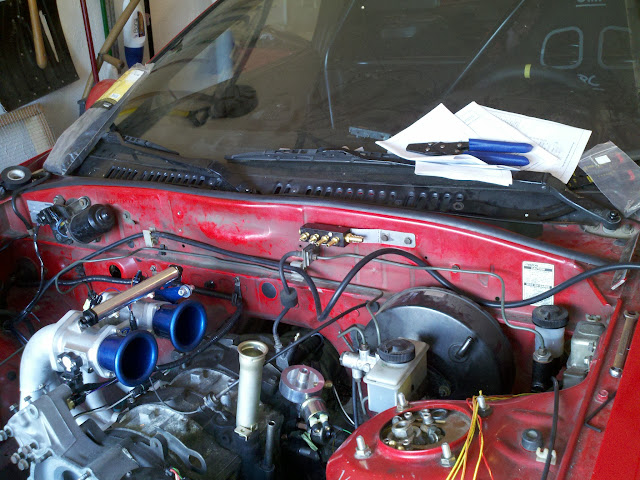 I would have preferred the vacuum block be more toward the passenger side but this was the easiest mounting point with existing holes. Don't worry, I will be installed a one-way check valve between the vacuum block and the brake booster, not like it'll see positive pressure anyway. I also put in my order for one of Defined Autoworks headers. They did my intake and my porting so why stop there? I've been thinking about ducting lately. I had always planned on ducting from the front bumper to the radiator and oil cooler but I was only going to have an e-fan (shrouded) on the backside. Now I'm thinking I might try to do some kind of hood duct exit system since I have all this new found space in front of the engine. Would it be better the duct the entire radiator surface area out the hood and just strap the e-fan on the back or still shroud the e-fan and run the duct from that shroud? My thoughts are the former would be better while the car is in motion while the latter would make the fan more effective when the car is idling. This car will see next to no stop/go traffic once it's done. |
|
|
|
06-21-2012, 01:09 PM
|
#44 |
|
The Newbie
Join Date: Jun 2012
Location: Somerset, KY
Posts: 7
Rep Power: 0 |
man what a nice build keep up the good work!
|
|
|
|
06-23-2012, 11:02 PM
|
#45 | |
|
IT'S ALIVE!
Join Date: Dec 2009
Location: Richmond, VA
Posts: 811
Rep Power: 16 |
Quote:
I finished the vacuum block last night and spent most of the day today finishing up the fuel lines and working out the vacuum line routing. Here's the "current engine bay" shot:  I decided to make a new fuel feed line (the one on about a 45 degree angle) after I took that picture. It held pressure just fine but I didn't like how it looked in the engine bay; like that matters! The new line is more aligned with the fuel return line. Here's why the vacuum lines took so long:  Left-to-right the vacuum port destinations are for the FPR, the ECU MAP sensor, intake runner #2 (vacuum source), intake runner #1 (vacuum source), and the brake booster.  It's hard to see from the pictures but all the vacuum lines are neatly secured to the firewall. Everything is nice and straight, and there are no kinks anywhere. I guess I had some OCD today; there are a lot of zip ties holding everything together! I also wrapped up the rest of the front wiring harness (headlights, horns, etc.) and attached it back to the stock mounting points. All that's left wiring-wise in the engine bay is the driver's side engine harness. |
|
|
|
|
| Bookmarks |
| Thread Tools | |
| Display Modes | |
|
|


 Linear Mode

