Go Back   Rotary Car Club > Tech Discussion > Transmission / Differential


Welcome to Rotary Car Club.

You are currently viewing our boards as a guest which gives you limited access to view most discussions and access our other features. By joining our free community you will have access to post topics, communicate privately with other members (PM), respond to polls, upload content and access many other special features. Registration is fast, simple and absolutely free so please, join our community today!

If you have any problems with the registration process or your account login, please contact contact us.

Reply
 
Thread Tools Display Modes
Old 09-25-2013, 09:52 AM   #1
infernosg
IT'S ALIVE!
 
infernosg's Avatar
 
Join Date: Dec 2009
Location: Richmond, VA
iTrader: (5)
Posts: 811
Rep Power: 15
infernosg is on a distinguished road
Default How to: Mazda Type M (N/A) Transmission Disassembly/Assembly

Background:

Earlier this year I swapped a Miata gear set into my N/A FC transmission. I photographed the entire assembly process pretty thoroughly and in the effort to bring more technical information to this site I'd like to document the process as a "how to." I'll be presenting this information as a disassembly, which is actually in the reverse order the photographs were taken.

Tools:

Surprisingly the transmission can be disassembled and reassembled with relatively simple tools. A set of good quality metric sockets and wrenches is invaluable. A hammer and punch are needed for several roll pins, and a torque wrench is a must if you are reassembling. Snap ring or c-clip pliers (both in- and out-springing) are also required. This process requires two SST's (special service tools): an extended 32 mm socket, and extended pullers. If you don't have access to the SST's it is possible to recreate them (see below).

Notes:

This task involves a huge number of parts. Many are specific to certain gears and must be disassembled in a certain order. Staying organized is key. In my pictures below you'll often see parts taped to a table with a number on it and sometimes I even specified what parts go with what gear. Also, you'll see in some pictures I'm wearing nitrile gloves. This is because I took these pictures during the reassembly process and I was trying to keep contamination to a minimum. If you're disassembling a transmission for the first time expect a dirty, smelly job.

Comment on model/year variation:

Mazda's Type M, "N/A," or "smooth" transmission has been in a lot of different RWD cars and trucks: '79-91 N/A RX-7's, '89-04 Miatas, and older B-series pickups to name a few. Because of this Mazda has made A LOT of small changes and revisions to these transmissions so depending on the year and model of your car your transmission could be slightly different but the overall process is the same. This is also working from USDM cars. I do not know how foreign models may differ.

Disclaimer:

Per standard forum practice I take no responsibility for any damage you may cause to your vehicle or its transmission. This is meant to be a visual guide to the dissasembly process documented in the 1989 Mazda RX-7 Factory Service Manual. Please consult this manual for the exact procedure as well as inspection, clearance, and fastener torque values.


Last edited by infernosg; 09-26-2013 at 06:49 AM..
infernosg is offline   Reply With Quote
Old 09-25-2013, 10:24 AM   #2
infernosg
IT'S ALIVE!
 
infernosg's Avatar
 
Join Date: Dec 2009
Location: Richmond, VA
iTrader: (5)
Posts: 811
Rep Power: 15
infernosg is on a distinguished road
Default Step 1: The Extension Housing

To start the transmission must be drained of all fluid and removed from the car. Refer to the FSM for the proper procedure. You should also remove all external sensors and fittings (5th/reverse switch, "over top" switch, speedometer driven gear and housing). If you plan on resting the transmission vertically, like I did below, be sure to put some blocks under the bell housing as the input shaft does protrude slightly beyond the bell housing flange.


The first disassembly procedure removes the extension housing or "tailshaft" housing as it's frequently described. The first step is to remove the spring and ball assembly located on the back side of the extension housing. This is located underneath the hex bolt shown below. There should be RTV sealing the bolt so it may require force to break loose. Be careful removing the bolt as the spring and ball are compressed.


The next step is to remove the "cap and spring assembly," which provides the return spring force for 5th and reverse gears. These are located under the black cap secured with two bolts in the picture above. Be careful as the spring is compressed. Cover removed:


Cover with bolt, spring, and steel ball previously removed:


Cover, spring, and "cap":


Assembly note: the steel ball rides over the steps in the cap shown above so when reassembling ensure these features are facing the rear of the transmission. You have to hold the control rod end in the 5th/reverse direction while installing the steel ball and spring to make sure it engages properly with the cap.

Next, the "inspection cover" is removed, which is held in place with four bolts and sealed with RTV.


Removing the inspection cover exposes the control rod end, which is held in place with a roll pin, and the 1st/2nd gear return spring.


Use a hammer and a punch to drive out the roll pin.

Note: the control rod end needs to be angled toward the "right" side of the transmission (as if shifting into 1st or 2nd gear) to give the roll pin enough clearance to back out. If this is not done it will bind on the extension housing case.

Remove the eight bolts holding the entire transmission housing assembly together. They are located at the extension housing forward flange, which mates with the 5th/reverse housing rear flange. They will have RTV on them.


With the bolts removed give the extension housing some taps, alternating sides, with a rubber hammer to break the RTV seal. You will be able to slide the extension housing off the rest of the transmission. Hold the control rod so it doesn't fall to the floor. This is everything disassembled so far:


Last edited by infernosg; 09-26-2013 at 09:18 AM.. Reason: Corrected spelling errors, corrected syntax, elaborated some steps
infernosg is offline   Reply With Quote
Old 09-25-2013, 10:26 AM   #3
infernosg
IT'S ALIVE!
 
infernosg's Avatar
 
Join Date: Dec 2009
Location: Richmond, VA
iTrader: (5)
Posts: 811
Rep Power: 15
infernosg is on a distinguished road
Default Step 2: The Bell Housing

Next is the front or "bell" housing. Remove the thrust bearing and clutch fork if not done already. This gives unobstructed access to the transmission front cover:


Undo the six bolts holding the cover in place. Be sure to keep track of any shims that may/may not come off with the cover. Be careful, the shims are very thin and can cut.


Assembly note: these shims are important as they set the forward bearing clearance (see FSM). Do not lose them!

Underneath are the two forward bearings: maintshaft on top, countershaft on bottom.


Note the c-clip rings on the mainshaft bearing and input shaft. These both need to be removed before the bell housing can be removed.

Note: Here is where some variation can occur. My original transmission had a small c-clip ring on the countershaft in front of the smaller bearing. The Miata countershaft I used to replace my original did not use a c-clip hence why it's not shown above. Make sure all c-clips are removed from the bearings and shafts before attempting to remove the bell housing. Also the bearing may or may not have "dust" covers like those shown above.

With the front cover and all c-clips removed the bell housing can be pulled off the rest of the assembly. Like the extension housing it is sealed with RTV so it'll take a few hits with a rubber mallet to break free. Depending on the age of the transmission the bell housing may slide right over the bearings or it could require some coersion. This is what's left:


Ignore the plug in the image above. The next step outlines the removal of the 5th/reverse gear housing, shift rods, and shift forks.

Last edited by infernosg; 09-26-2013 at 09:03 AM.. Reason: Corrected spelling errors, corrected syntax, elaborated some steps
infernosg is offline   Reply With Quote
Old 09-25-2013, 10:28 AM   #4
infernosg
IT'S ALIVE!
 
infernosg's Avatar
 
Join Date: Dec 2009
Location: Richmond, VA
iTrader: (5)
Posts: 811
Rep Power: 15
infernosg is on a distinguished road
Default Step 3: 5th/Reverse Housing

Note: before I get into the next disassembly step I want to address a difference between transmissions that may be encountered. Some transmissions, specifically S5 N/A transmissions, have a very large nut, weight, and c-shaped, wedge spacers on the mainshaft just in front of the speedometer drive gear. My understanding is this was added to damp vibrations caused by the higher engine speeds in those cars. I chose to go with the Miata mainshaft and forgo this weight at the recommendation of Mazdatrix who has been using this setup in their race cars for years without issue. If your transmission has these parts they're easy to remove (I used a large, adjusting wrench) but make sure you keep everything organized for resassembly.

Before the 5th/reverse gear housing can be removed there are some obstacles that must be cleared. Starting at the back the first is the speedometer drive gear. It's held in place with two snap rings.


Remove the rear snap ring and slide the gear off the mainshaft. Be careful not to lose the steel ball underneath that prevents the gear from spinning independently of the mainshaft.


Speedometer drive gear, snap rings, and steel ball:


Assembly note: there is no forward or rear on the drive gear. It can be reinstalled either way.

Next are the shift rod ends. Each of these is held in place with a roll pin. Using a hammer and punch drive out each pin and slide off the rod end. Start with 1st/2nd:


Next is 3rd/4th:


Last is 5th/reverse:


Assembly note: when reinstalling the roll pins make sure the "break" is facing forward or rearward (parallel to the axis of motion). This also applies to the roll pin in the control rod end removed earlier.

With the rod ends removed there should be nothing remaining in the way of the 5th/reverse housing. As with the extension housing and bell housing this is sealed to the bearing plate with RTV. Apply alternating taps with a rubber hammer and it will break loose. Slide it off the mainshaft and the "guts" of the transmission are completely exposed.


Last edited by infernosg; 09-26-2013 at 09:22 AM..
infernosg is offline   Reply With Quote
Old 09-25-2013, 10:29 AM   #5
infernosg
IT'S ALIVE!
 
infernosg's Avatar
 
Join Date: Dec 2009
Location: Richmond, VA
iTrader: (5)
Posts: 811
Rep Power: 15
infernosg is on a distinguished road
Default Step 4: Shift Rods and Forks

The next step outlines the removal of the shift rods and forks. First, remove the c-clip and spring from the forward side of the 5th/reverse rod. Be careful as the the spring is compressed. This relieves the tension on the 5th/reverse shift rod.


Note: depending on the year and model of your car this assembly might be slightly different. Regardless the function is the same. This spring is also the source of the dreaded "5th into reverse lock" experienced by some RX-7 and Miata owners. Basically, when shifting too quickly from 5th into neutral the spring tension combined with momentum can cause the shift rod to continue moving forward and shift the car into reverse despite the shift lever being in the neutral position resulting in the car being "locked" in reverse.

The shift rods are supported by a series of springs and steel balls, which are covered by bolts. There are three and they're shown below.


Underneath each bolt you'll find the spring and steel ball:


Note: the spring for the 5th/reverse shift rod is slightly different than the other two. Be sure to keep it separate.

All bolts, springs, and balls removed:


In the picture above I've also removed a c-clip from the 1st/2nd shift rod. It fits in the groove between the shift fork and the bearing plate.

Note: here again can be some differences between models and years. My original RX-7 transmission had c-clips on the shift rods in front of the bearing plate for both 1st/2nd and 3rd/4th. The Miata set replacing everything only use a c-clip on 1st/2nd.

The next step is to drive out the roll pins holding the shift forks to the rods. Remove with hammer and punch.

Assembly note: again make sure roll pin break is aligned with direction of rod movement when reinstalling.

With the shift forks disconnected the rods can be removed in the order shown below. This is accomplished by sliding them through the bearing plate and accompanying shift fork. 1st/2nd shift rod removed:


The reason these are pulled in a specific order is because the shift rods are supported between each other with a little steel cylinder with hemispherical ends. It's barely visible in the picture below showing the interface between the 1st/2nd rod and the 3rd/4th rod.


This is the piece in question:


There are two: one between 1st/2nd and 3rd/4th and one between 3rd/4th and 5th/reverse and they are identical, but you may want to note their position anyway. My understanding is when the transmission is placed in one gear (say, 1st) that particular shift rod (1st/2nd) pushes up and down on these pieces locking the other shift rods (3rd/4th and 5th/reverse) in place to prevent multiple gear engagement. 3rd/4th shift rod removed:


Little cylinder between 3rd/4th and 5th/reverse:


Note: there may also be a smaller cylinder-like piece that sits inside a hole bored through the shift rod itself. Unfortunately I did not take a picture of this and it is not referenced in the RX-7 FSM. I can't recall if it was in the 1st/2nd or 3rd/4th rods or both. This is probably another one of the little differences between models and years. Just be careful, take your time removing everything, and keep parts for each gear pairing together.

Last is the 5th/reverse rod, which is a little different. As with the others slide the rod out through the bearing plate and fork...


...but do so slowly because there is an additional spring and ball hiding underneath:


Spring and ball removed:


Note: be sure to keep this spring separate from the others as it's different.

Now the shift forks can be removed from their respective clutch hubs. This leaves an assembly that looks like the following:


Note my method of organization (numbers correspond to assembly order in the FSM).

Last edited by infernosg; 09-26-2013 at 09:50 AM.. Reason: Corrected spelling errors, corrected syntax, elaborated some steps
infernosg is offline   Reply With Quote
Old 09-25-2013, 10:32 AM   #6
infernosg
IT'S ALIVE!
 
infernosg's Avatar
 
Join Date: Dec 2009
Location: Richmond, VA
iTrader: (5)
Posts: 811
Rep Power: 15
infernosg is on a distinguished road
Default Step 5: Rear Bearings, 5th, Reverse, and 4th Gears

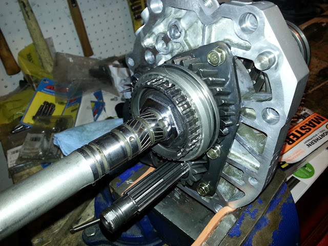
All that's left is the gear and shaft assembly itself. The next step in the process is to remove the rear bearings and the 5th and reverse gear assembly allowing the mainshaft and countershafts to be removed, which then frees 4th gear.


Note: bearings may be with or without dust shields. My RX-7 had them on on both rear bearings but the Miata (shown above) doesn't despite being newer.

First remove the countershaft rear nut and bearing to get them out of the way of the mainshaft pieces. In order loosen the nut lock the transmission into both 1st and reverse by sliding the respective clutch hubs into position. This allows you to apply torque to the rear nut without the transmission spinning. The nut is staked so you will need drive that out with a punch or screwdriver. The nut is also installed with a lot or torque so clamp the assembly down and use a breaker bar. Once the nut is removed the bearing can be pulled off with a normal two- or three-jaw puller.


Next is the mainshaft rear bearing. First remove the c-clip.


Then the small spacer behind it.


This exposes two thick c-shaped washers held by a retaining ring. Remove these to get to the mainshaft rear bearing.


Assembly note: keep track of the spacer and c-shaped washers. They are specific thicknesses and are needed to set the clearance for the rear bearing (see FSM).

Here is where the first SST comes in. The actual Mazda SST is a bearing puller with very long arms. Since I don't have access to these SST's I had to get creative. Fortunately I stumbled across a fellow forum member who went through this same process and came up with his own SST: a modified, two-jaw puller:


Basically, it's a simple two-jaw puller with the normal arms replaced by long steel flatstock. I forget the actual length but I think somewhere around 17 inches was required. With this tool the bearing is removed exposing another set of c-washers and retaining ring and it allows access to the countershaft 5th gear companion.


The countershaft gear slips off easily revealing a long tube spacer.


Remove the tube spacer but leave the countershaft reverse gear in place as it's required to keep the assembly from spinning. Jump back to the mainshaft and remove the c-washers and retaining ring that were behind the bearing. This exposes a thick spacer.


Assembly note: as with before keep these c-washers and spacer straight as they're needed to set proper clearances.

The spacer slides right off but like the speedometer drive gear it also has a small steel ball underneath it.


Assembly note: keep track of that spacer!

Now 5th gear and its syncho can be removed. They should slide easily off the mainshaft. Be careful not to mar any surfaces especially the synchro!. If you removed the assembly from the vice like I did you'll need to get it back in there for the next step.


With 5th gear gone the notorious transmission rear nut is exposed. Here is where SST number two comes into play. The actual SST is a very deep-well 32 mm socket. Again, I don't have access to one so I got creative. The same forum member came to the rescue with a hacked and spliced 32 mm socket and tube.


This nut is held on with even more torque than the countershaft nut so expect to spend some time here.

Note: I had an even more difficult time torquing the nut during reassembly because the Miata reverse gear is helical. This meant every time I tried to torque the nut the countershaft reverse gear would try to walk its way out allowing the mainshaft to spin. The RX-7 reverse gear was straight cut so there was no forward or rearward forces trying to move the gear. I find it interesting not only is the reverse ratio different but the cut is as well.

With the nut off the 5th/reverse clutch hub is exposed. Using the same long-arm puller above lock onto the hub being careful not to damage the brass syncho on the other side and remove.


Note: during the disassembly process I found it easier to disassemble the clutch hub while it was on the mainshaft. This gave more surface area to grab with the puller. I will explain the disassembly of a clutch hub at the end.

Now the reverse gear and its syncho can be removed. Unlike 5th gear, reverse has a needle bearing and inner bearing race underneath it. Needle bearing:


Inner race:


Inner race removed:


Note: there is also likely a spacer between the reverse gear and the middle bearing. Remove this and keep track of it as it's needed to set clearance during reassembly (see FSM).

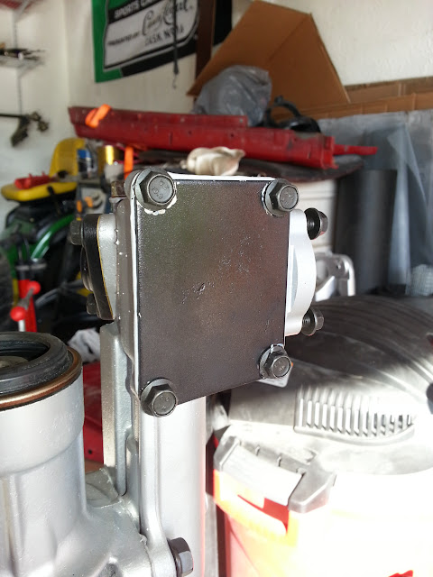
Next is the countershaft reverse companion gear. When trying to remove this gear I noticed the bearing plate cover interfered so I had to remove the cover. In order to remove the cover undo the bolts and pull it off. With the cover removed the countershaft reverse gear can be removed along with the idler gear and its two spacers.


Note: I don't believe the RX-7 FSM says the bearing plate cover has to come off. It's possible the different reverse ratio of the Miata makes this not possible where it is with the RX-7. Either way, don't forget to keep track of the spacers for the idler gear.

Now the mainshaft and countershaft can be separated from the bearing plate. Both have to move together to be removed. In my case the mainshaft separated easily but the countershaft didn't want to budge. I ended up having to use the puller to "pull" the bearing plate off the countershaft and even then the bearing was still stuck on the countershaft. Keep track of any spacer on the forward side of the bearing plate as it works with the previous rear spacer to set clearances. Be careful once the three are separated as 4th gear and its synchro are no longer supported and can simply fall off the mainshaft.

4th gear slides off the front of the mainshaft easily. Be sure its syncho and needle bearing come with it.


Exploded:


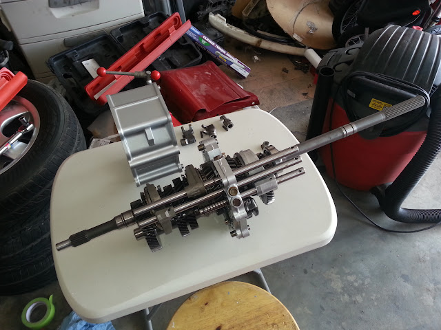
At this point the transmission has been reduced to this:


Note: there are lots of specific spacers and washers that are removed during this step. Keep track of them and their location for reassembly. If you are replacing parts (I did not) different thicknesses are offered to properly set bearing clearances.

Last edited by infernosg; 09-26-2013 at 10:16 AM.. Reason: Corrected spelling errors, corrected syntax, elaborated some steps
infernosg is offline   Reply With Quote
Old 09-25-2013, 10:33 AM   #7
infernosg
IT'S ALIVE!
 
infernosg's Avatar
 
Join Date: Dec 2009
Location: Richmond, VA
iTrader: (5)
Posts: 811
Rep Power: 15
infernosg is on a distinguished road
Default Step 6: Mainshaft and Forward Gear Assembly

The most daunting steps are done. From here it's a matter of sliding gears and clutch hubs off the mainshaft. Be careful handling the mainshaft to avoid dinging any surfaces and be mindful that 1st gear is no longer supported to the rear.

With 4th gear, its bearing, and synchro removed support the mainshaft assembly with the front pointing downward. Again, there will be a small spacer between 1st gear and the bearing plate. Remove this and note its location for reassembly.


Like reverse, 1st gear and its synchro are easily removed and are supported by a needle bearing and inner bearing race. Slide 1st gear and its synchro off the back of the mainshaft being careful not to ding any surfaces.


Needle bearing removed exposing inner race:


Remove the inner race and flip the mainshaft around to work on the forward side.


As with the 5th/reverse clutch hub pull the 3rd/4th hub off from the front of the mainshaft. Again, it's probably easier to pull the hub apart to avoid damaging anything. You can use a puller but I used a 1/8" piece of flat stock that I laid on the hub surface and tapped with a hammer, alternating sides. 3rd/4th clutch hub removed:


3rd gear is like 5th gear in that it spins around the mainshaft with no needle bearing support. Slide 3rd gear and its synchro off the front of the mainshaft and the forward side is complete. Flip the mainshaft around one more time to get to the 1st/2nd clutch hub.


Remove the 1st/2nd clutch hub using the modified puller or by lightly tapping on a piece of soft(er) metal with a hammer, alternating sides.


2nd gear is like 3rd and 5th in that it does not have a needle bearing and inner race. Slide 2nd gear and its synchro off the rear of the mainshaft and the mainshaft is completely disassembled.


Note: Sometime in the early-mid '90's Mazda added a second synchro to 2nd gear in the Type M transmissions. This is seen in the pictures above. This does not affect the disassembly process but means there are more parts.

This is basically the end of the disassembly process. Assembly is really the reverse but with clearance checks and torquing fasteners required. Be sure to inspect all bearing surfaces, synchro surfaces, gear teeth, clutch hub teeth, and other parts per the FSM prior to reassembly.

Assembly note: to reinstall clutch hubs and bearings I made my own driver out of steel pipe. I purchased two 1 ft sections of 2.5 in. pipe and cut the threads off the end of one. I also purchased a straight coupler so I could adjust the length between 12" and 24" and an end cap to use as a hammering surface.

Short version:


Long version:


The next section is pretty much optional. I'll go into detail regarding the disassembly of the bearing plate and clutch hubs.

Last edited by infernosg; 09-26-2013 at 12:16 PM.. Reason: Added info.
infernosg is offline   Reply With Quote
Old 09-25-2013, 12:40 PM   #8
infernosg
IT'S ALIVE!
 
infernosg's Avatar
 
Join Date: Dec 2009
Location: Richmond, VA
iTrader: (5)
Posts: 811
Rep Power: 15
infernosg is on a distinguished road
Default Step 7: Bearing Plate

If you intend to disassemble the bearing plate further (i.e. for center bearing replacement) and/or took apart one or more clutch hubs please read on.

Depending on your reverse gear your bearing plate is either still completely assembled or partly disassembled with the cover off. Completely assembled:


Partially disassembled:


Assuming your bearing plate is fully assembled start by removing the 6 bolts, noting two are different, to remove the cover.


Next, remove the idle gear and its two spacers. It's probably not required but I made note of which spacer was on each side and its orientation. Now the assembly looks like the second picture above. Again, you may already be at this step.

Note the main bearing can only be pushed out through one side. Support the bearing plate and use whatever method you prefer to drive it out.


The center countershaft bearing has a c-clip around it. The c-clip does not need to be removed to push out the bearing. Both bearings removed:


Bearings with c-clips and shims:


The shims fit between the bearing plate lip and the mainshaft center bearing and the c-clip and bearing plate for the countershaft bearing. Again, clearances (consult FSM). These can also be sharp so be careful. If you want to go further you can unbolt and remove the idler gear shaft but I did not do that.

If you took apart a clutch hub to remove it or are just curious about how they work work read on. All of the clutch hubs are basically the same with the only real difference being size.


Each clutch consists of a inner hub, which is fixed to the mainshaft, an outer locking ring, which serves to connect the hub with the drive gear, three keys to control the outer ring's movement, and two wire springs to hold the keys in place. To disassemble, if not done already, simple slide the outer ring off the inner hub making sure none of the keys or springs going flying off into space.


If you look at the ID of the hub you notice one side is chamfer and the other isn't. Pay attention to this when installing as the chamfers must point a certain way (check the FSM).

Assembly note: reassembling the clutch is fairly straightforward but there is a "right" way to do it. Place the keys in the outer grooves in the hub with the taller, center section pointing outward. You'll notice some of the teeth in the outer ring are missing a center section. Align these modified teeth with the keys and slide the outer ring over the hub. Lastly, install the wire spring by inserting the bent end into the hole and winding it around the hub. The wire must contact each key and must be "inside" the inward-pointing sections on the keys. It's a little tricky as one side often comes undone when you try to do the other.

That's pretty much it. I see this has already been made a sticky so that's a start. Feel free to ask any questions!

Last edited by infernosg; 09-26-2013 at 12:45 PM.. Reason: Added content
infernosg is offline   Reply With Quote
Old 09-25-2013, 03:09 PM   #9
My5ABaby
Sigh.....
 
My5ABaby's Avatar
 
Join Date: Feb 2008
Location: Murfreesboro, TN
iTrader: (6)
Posts: 2,377
Rep Power: 19
My5ABaby will become famous soon enough
Default

Wow, this is probably the most detailed write up I've seen. Well done.
__________________
1986 Sport: 132k miles, 5A (Sapphire Blue Metallic), Tokico Blues, Racing Beat Springs, Custom LED tailights (only S4 LED tails in the world), SSR Mark II, Racing Beat exhaust, S5 black interior, Rotary Resurrection rebuild at 120k miles

Community Service Manual

RotorWiki

"Imagination costs nothing; we could build square locomotives or fly to Mars" - Felix Wankel

Yesterday is history, tomorrow is a mystery, but today is a gift. That is why it is called the "present."
My5ABaby is offline   Reply With Quote
Old 09-25-2013, 04:20 PM   #10
Rotary Evolution
rotaryevolution.net
 
Rotary Evolution's Avatar
 
Join Date: Feb 2011
Location: Las Vegas, NV
iTrader: (0)
Posts: 248
Rep Power: 14
Rotary Evolution is on a distinguished road
Default

most of the steps are the same for the turbo transmission as well except the last step is walking the main gear sets out of the case once all other steps are complete. it has to remain inside the box until the back is disassembled.
__________________
http://rotaryevolution.net
Rotary Evolution is offline   Reply With Quote
Old 09-25-2013, 08:51 PM   #11
JL1RX7
Rotary Fanatic
 
Join Date: Feb 2008
Location: Front Royal, VA
iTrader: (1)
Posts: 487
Rep Power: 17
JL1RX7 will become famous soon enough
Default

Mods can we get this stickied so it is always at the top. Great write up! Thank you for the hard work.
JL1RX7 is offline   Reply With Quote
Old 09-25-2013, 09:40 PM   #12
RETed
RCC Addict
 
Join Date: Mar 2008
Location: Honolulu, Hawaii USA
iTrader: (1)
Posts: 1,813
Rep Power: 18
RETed will become famous soon enough
Default

Agreed.
Who is doing the pic hosting?
I hope someone can mirror this write-up later?
I would for the write-up to end up like TTT's power-to-manual steering rack conversion where we lost some of the original pics.


-Ted
__________________
reted_2000@yahoo.com
Technical Advisor
FC3S Pro
http://fc3spro.com/


Quote:
Originally Posted by TitaniumTT View Post
because you're only as good as your backup
RETed is offline   Reply With Quote
Old 09-26-2013, 07:16 AM   #13
infernosg
IT'S ALIVE!
 
infernosg's Avatar
 
Join Date: Dec 2009
Location: Richmond, VA
iTrader: (5)
Posts: 811
Rep Power: 15
infernosg is on a distinguished road
Default

Quote:
Originally Posted by My5ABaby View Post
Wow, this is probably the most detailed write up I've seen. Well done.
Thanks! I've been sitting on this a while and got some free time to start putting everything together. I know it isn't very technical, but the FSM is actually very good in this respect. I just find the diagrams lacking sometimes hence why I made this.

Quote:
Originally Posted by JL1RX7 View Post
Mods can we get this stickied so it is always at the top. Great write up! Thank you for the hard work.
Thanks! I'm still making some tweaks to my initial posts and I've got to finish the last few steps though.

Quote:
Originally Posted by RETed View Post
Agreed.
Who is doing the pic hosting?
I hope someone can mirror this write-up later?
I would for the write-up to end up like TTT's power-to-manual steering rack conversion where we lost some of the original pics.


-Ted
Right now I'm linking to one of my public Picasa galleries. It's the same one I use to document my current build. I hasn't failed me yet but I would love a more permanent solution. I too was disappointed some pics were lost in the steering rack thread although it wasn't too hard to figure out. I'm open to suggestions.
infernosg is offline   Reply With Quote
Old 09-26-2013, 01:46 PM   #14
infernosg
IT'S ALIVE!
 
infernosg's Avatar
 
Join Date: Dec 2009
Location: Richmond, VA
iTrader: (5)
Posts: 811
Rep Power: 15
infernosg is on a distinguished road
Default

Last steps completed.
infernosg is offline   Reply With Quote
Reply

Bookmarks


Posting Rules
You may not post new threads
You may not post replies
You may not post attachments
You may not edit your posts

BB code is On
Smilies are On
[IMG] code is On
HTML code is Off

Forum Jump


All times are GMT -5. The time now is 12:56 AM.


Powered by vBulletin® Version 3.8.4
Copyright ©2000 - 2024, Jelsoft Enterprises Ltd.
Hosted by www.GotPlacement.com
Ad Management by RedTyger