Go Back   Rotary Car Club > Tech Discussion > Piston Engine Conversion

Piston Engine Conversion Have you replaced your rotary with a V8 or any other type of piston engine? Tell us about it!


Welcome to Rotary Car Club.

You are currently viewing our boards as a guest which gives you limited access to view most discussions and access our other features. By joining our free community you will have access to post topics, communicate privately with other members (PM), respond to polls, upload content and access many other special features. Registration is fast, simple and absolutely free so please, join our community today!

If you have any problems with the registration process or your account login, please contact contact us.

Reply
 
Thread Tools Display Modes
Old 11-16-2012, 10:46 AM   #16
StephenSheppard
Rotary Fan in Training
 
Join Date: Nov 2012
iTrader: (0)
Posts: 58
Rep Power: 12
StephenSheppard is on a distinguished road
Default

Also this


StephenSheppard is offline   Reply With Quote
Old 11-16-2012, 11:03 AM   #17
StephenSheppard
Rotary Fan in Training
 
Join Date: Nov 2012
iTrader: (0)
Posts: 58
Rep Power: 12
StephenSheppard is on a distinguished road
Default

A couple vids of the flimsiness of things at this point, incase anyone had any great ideas about cutting their car up to this extent without bracing anything.


A vid of the brake line grommet to give you a better idea of what I'm talking about with trimming the nose of the grommet.

StephenSheppard is offline   Reply With Quote
Old 11-16-2012, 12:16 PM   #18
StephenSheppard
Rotary Fan in Training
 
Join Date: Nov 2012
iTrader: (0)
Posts: 58
Rep Power: 12
StephenSheppard is on a distinguished road
Default

Going to knock out some of this simple stuff today.
Attached Files
File Type: pdf Wiper fan sub harness diagram.pdf (153.2 KB, 3 views)
StephenSheppard is offline   Reply With Quote
Old 11-16-2012, 09:25 PM   #19
mattallac
Rotary Fanatic
 
mattallac's Avatar
 
Join Date: Aug 2011
Location: crockett ca.
iTrader: (1)
Posts: 176
Rep Power: 0
mattallac is on a distinguished road
Default

lookin pretty cool , I also have an fc but its a vert and i am also going to sbc or ls1 ( iron block truck) for drifting . how bad is the expense to do this kind of swap ? the drift car i am finishing now is a 79 glc sport with a 12a . good luck with the build , I have been watching this thread since you started , great info .
mattallac is offline   Reply With Quote
Old 11-16-2012, 10:02 PM   #20
josh18_2k
Rotary Fanatic
 
Join Date: Feb 2008
Location: Gresham, OR
iTrader: (0)
Posts: 473
Rep Power: 17
josh18_2k is on a distinguished road
Default

why did you even keep that sheetmetal crossmember? i cut that crap out, mounted the radiator at 45*


__________________
josh18_2k is offline   Reply With Quote
Old 11-18-2012, 06:50 AM   #21
StephenSheppard
Rotary Fan in Training
 
Join Date: Nov 2012
iTrader: (0)
Posts: 58
Rep Power: 12
StephenSheppard is on a distinguished road
Default

The top radiator support is just there for a locating / referencing point mostly. I may or may not cut it out. Rememeber I'm building all this stuff with no engine in the car, so you sorta need to know where some things are at least lol. If I keep it I will of course make it less flimsy.


Cost of this? I don't have a clue. I always go to far and I always spend too much. I'm not much of a budget building kind of person. Mine won't be cheap, someone else could make a running car pretty quickly if the car was already painted, hadn't been wrecked in the front end, etc. To give you an idea I have a $220 battery (AGM) in like a $150 battery box, or whatever it costs with all the parts lol. You get the point I think.

Even though this car is probably destined to be totalled I still don't have the ability to let myself slap it together and not care what the outcome looks like.
StephenSheppard is offline   Reply With Quote
Old 11-19-2012, 09:12 AM   #22
StephenSheppard
Rotary Fan in Training
 
Join Date: Nov 2012
iTrader: (0)
Posts: 58
Rep Power: 12
StephenSheppard is on a distinguished road
Default

I'm not sure what the deal was, but photobucket was being weird for a day or so and not letting me upload anything.

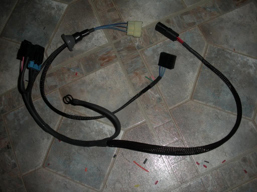
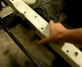
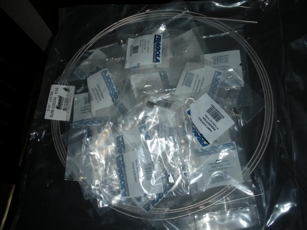
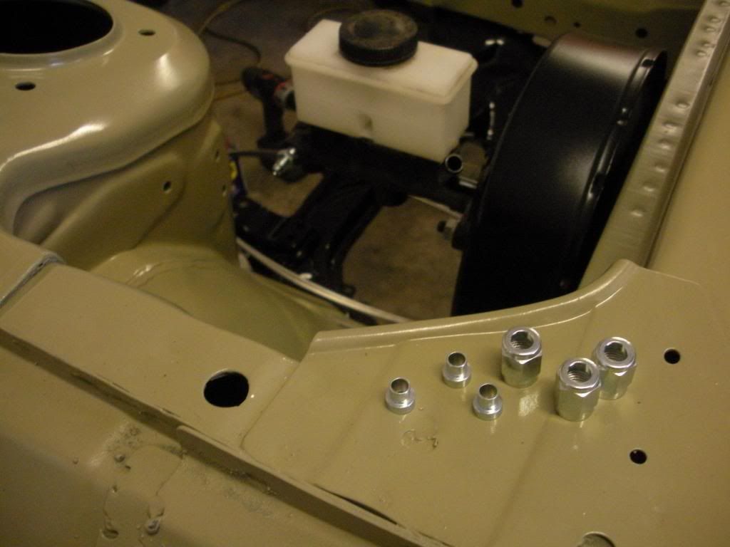
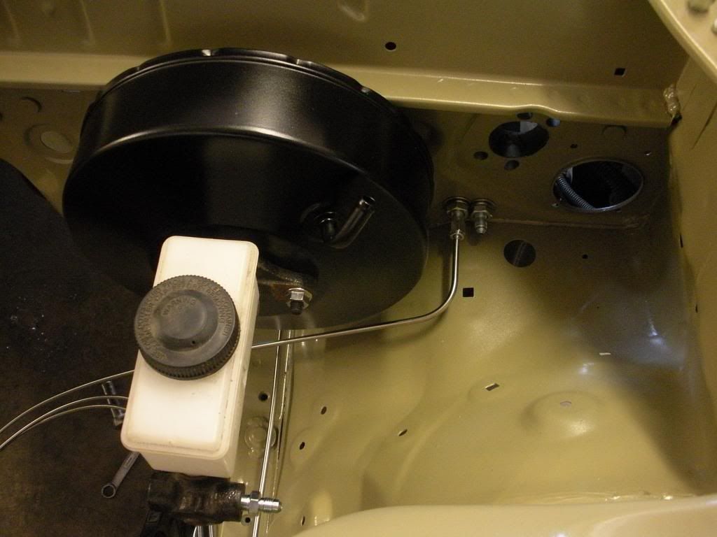
Anyways here's a couple terrible pics of the little sub harness I made from the diagram up there^. I did however decide to add an additional connector that the 12V for the and start signal would be terminated in. makes the harness easier to take apart, install, and troubleshoot. Should a problem arise.


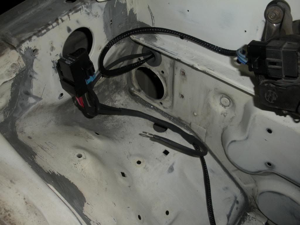
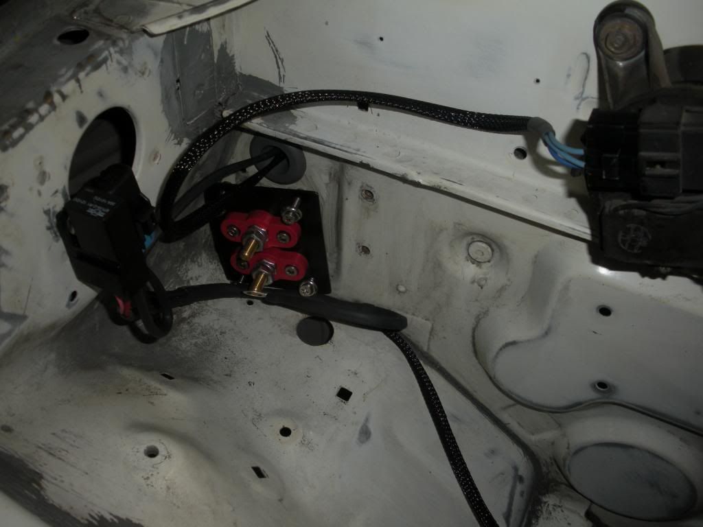
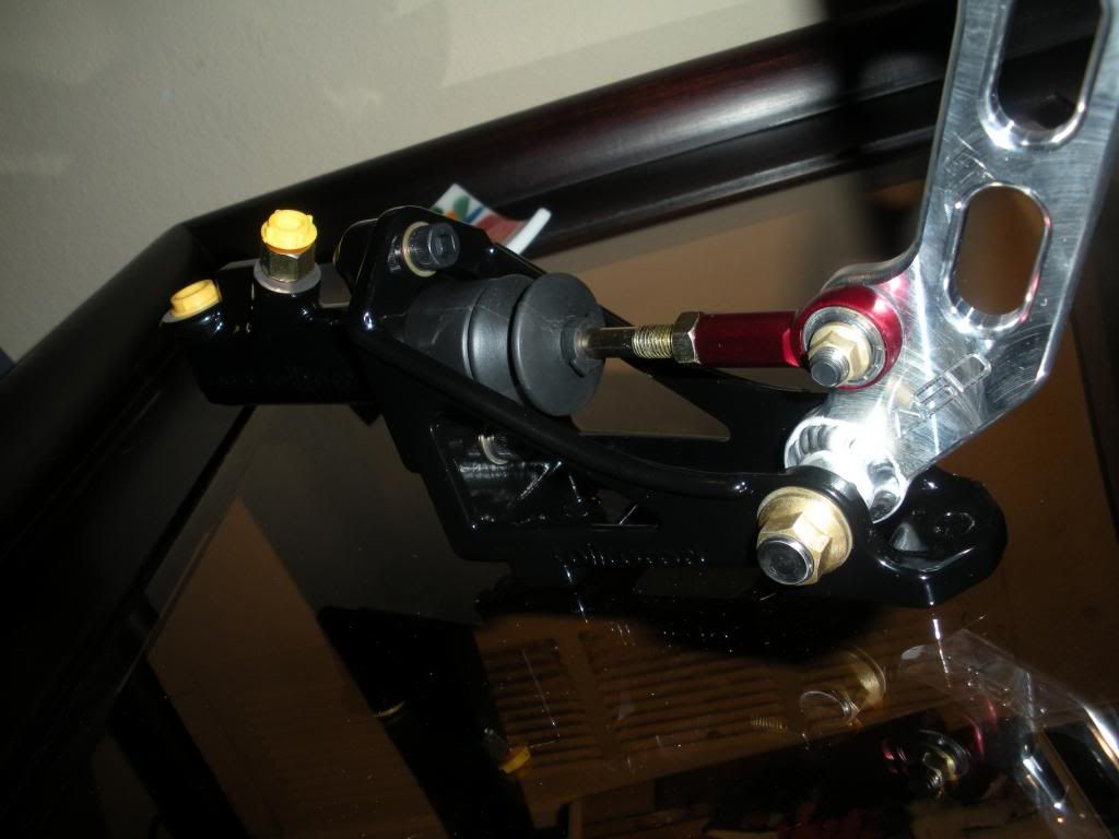
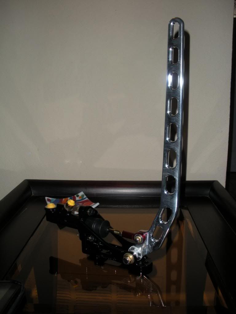
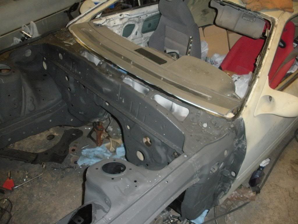
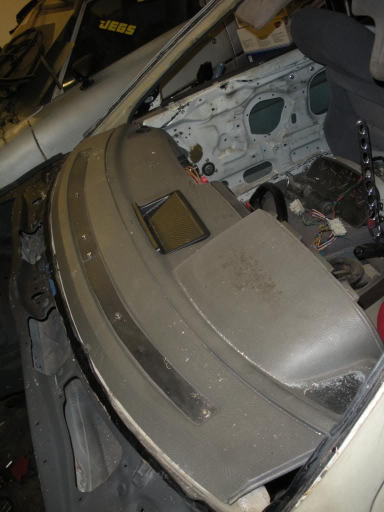
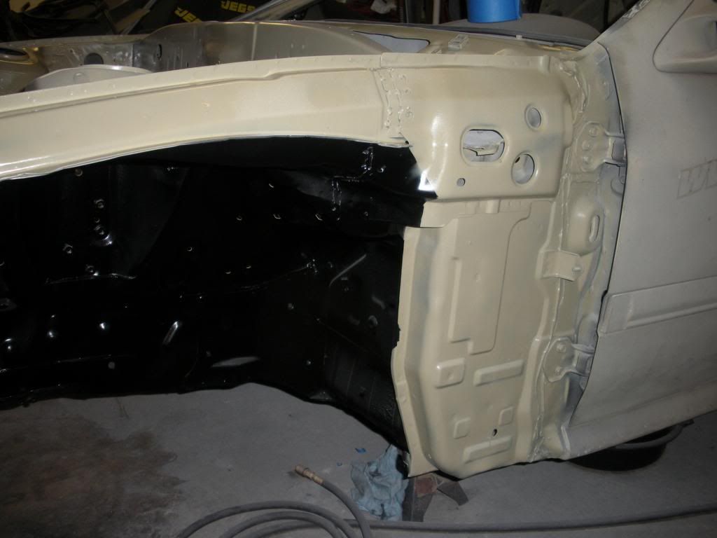
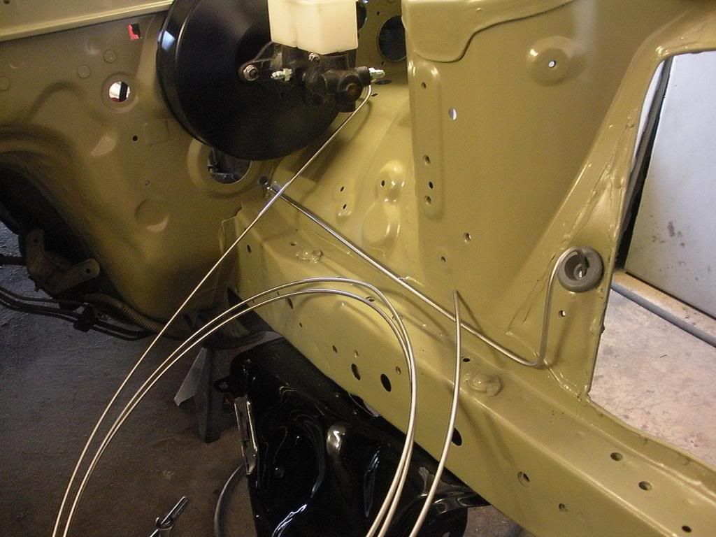
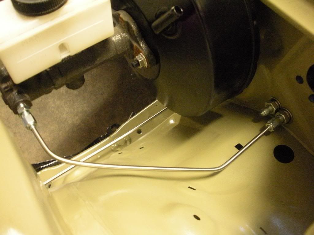
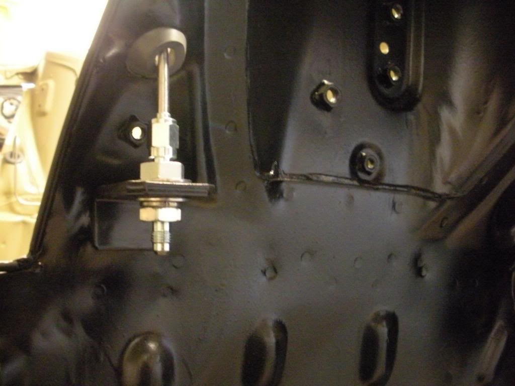
In these next two pics there are no pop-in ziptie holders or anything since I still have to paint the engine bay. Also the red pass thrus remember are mounted to the backside of the firewall not the front like the picture. Just kind of put it there for explanation's sake is all.


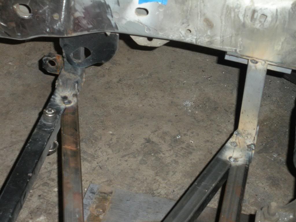
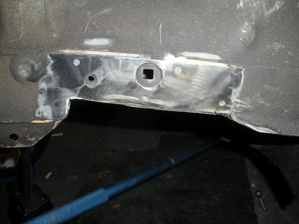
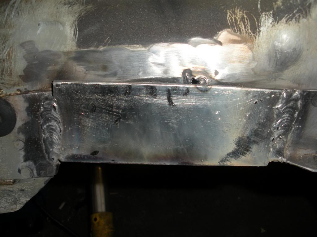
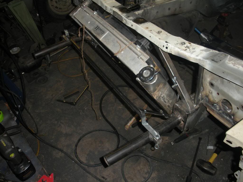
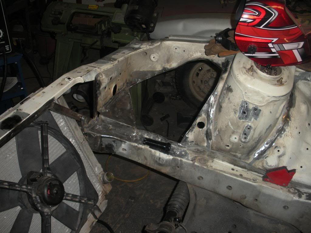
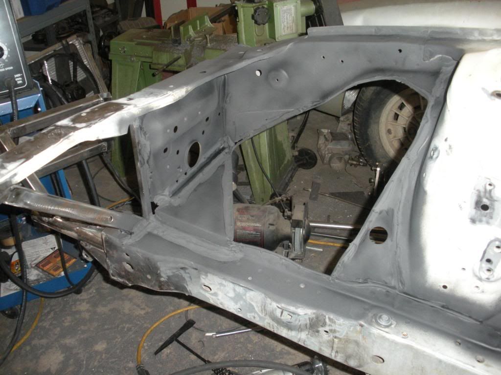
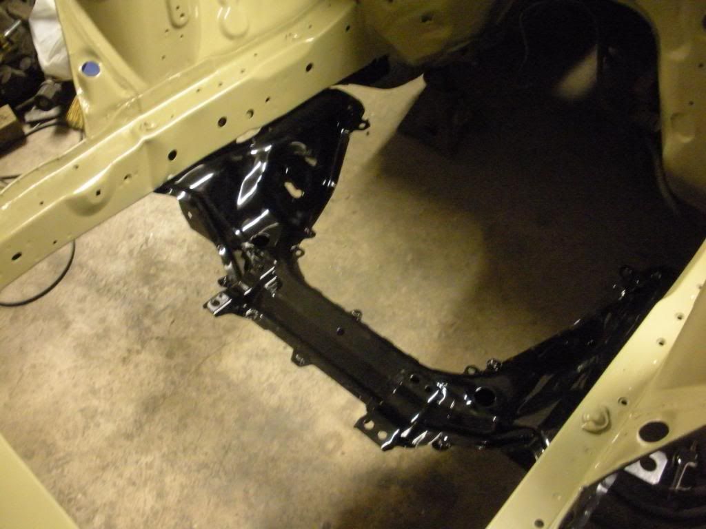
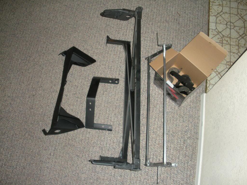
I borrowed a little flux core wire feed welder to start tacking stuff together for the front end. Don't judge me :P lol


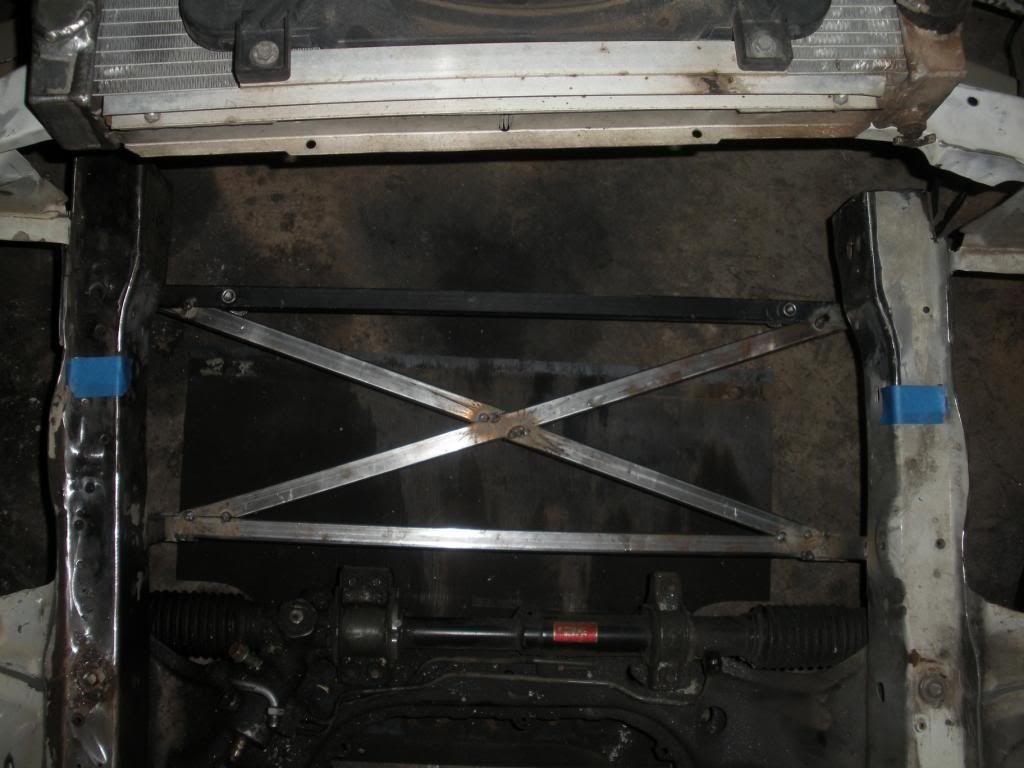
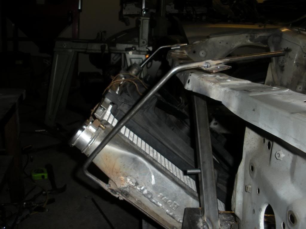
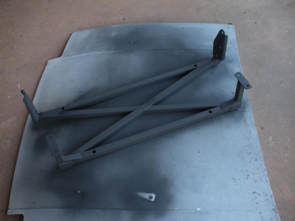
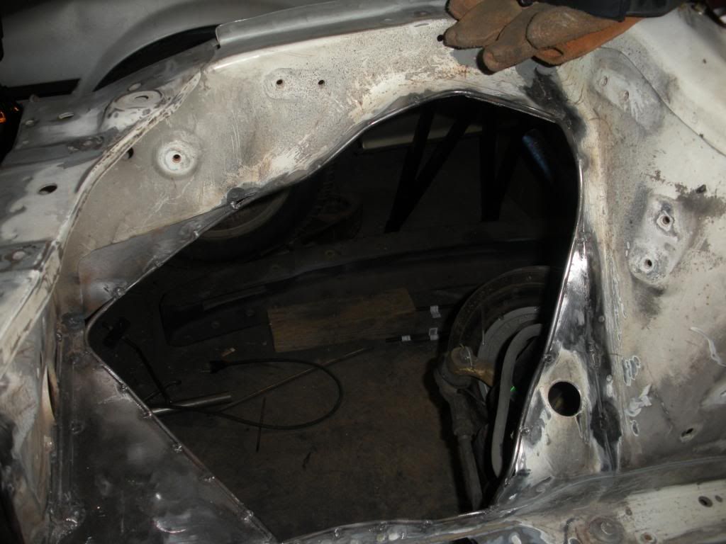
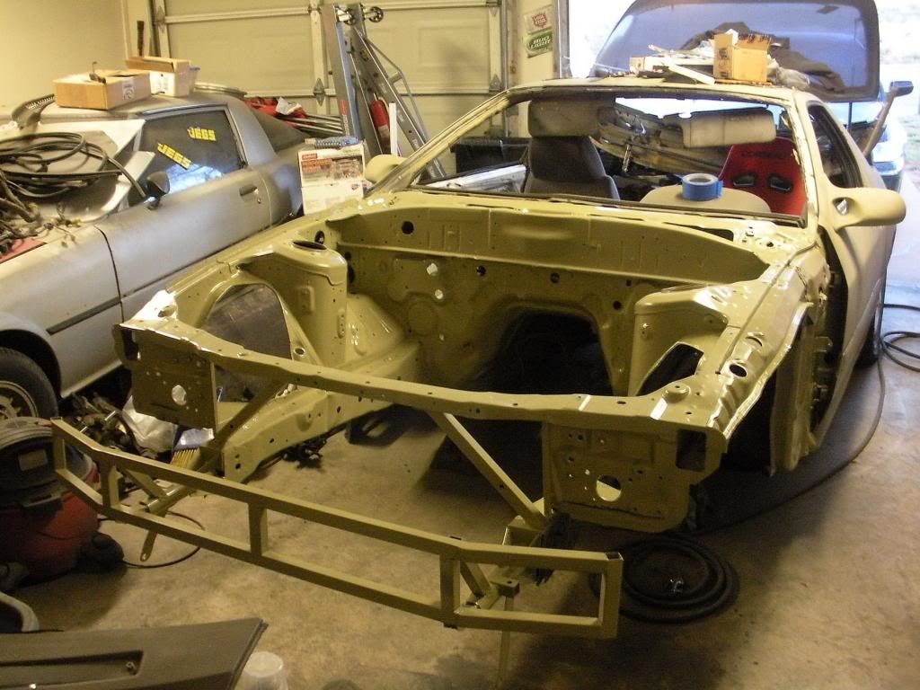
All that will be finish welded. It all unbolts from the front of the car. At the tow hook position and the swaybar position. Obviously not finished yet but I needed to get that put together so I could start mocking up the radiator mounting stuffs.

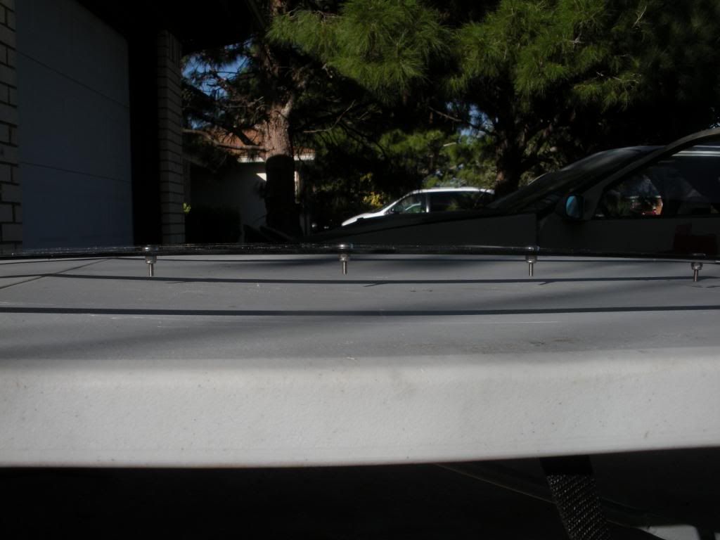
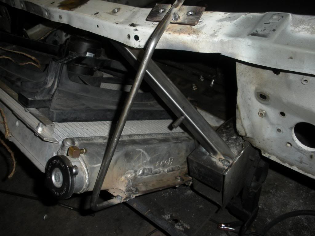
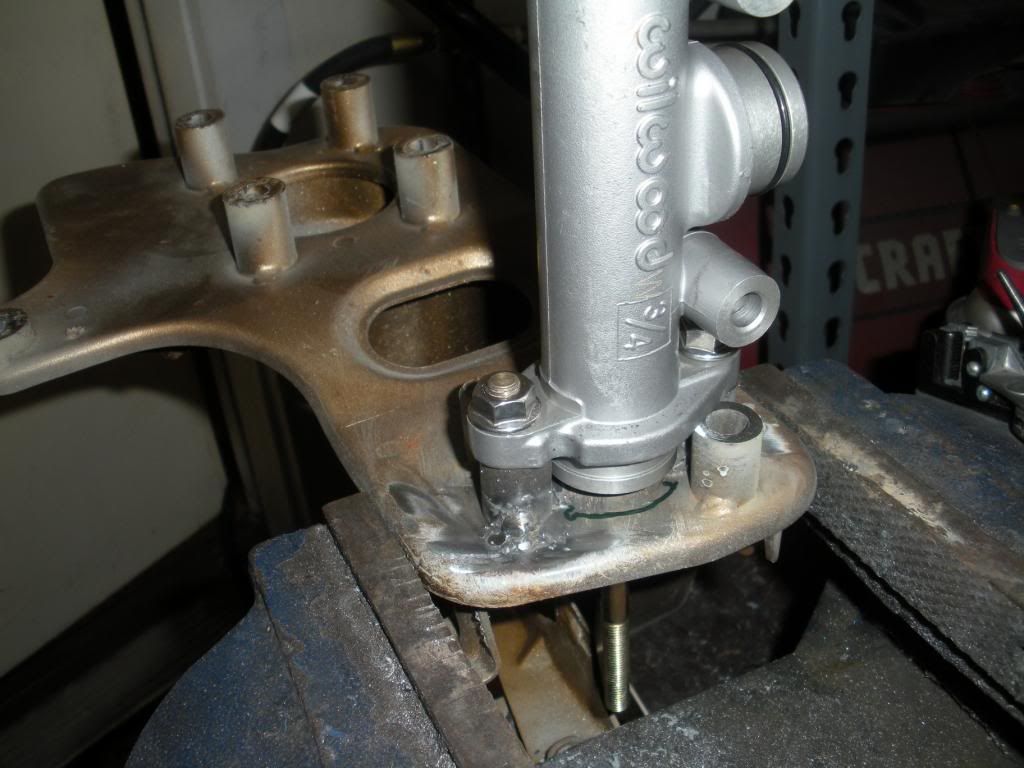
Basically there's a piece of 1" angle iron bolted to the swaybar bracket holes, then the square tube comes up and meets it there. I finish weldign this thing off the car. I'll try to remember to weigh it for those thinking it's super heavy or whatever. The point of this is two fold: First it should be strong enough to make up for me cutting the cross tube out of the front there, and 2nd it holds the back of the splitter up and a panel in place to keep stuff from bouncing up into the engine bay. Anti-intrusion guard if you will.


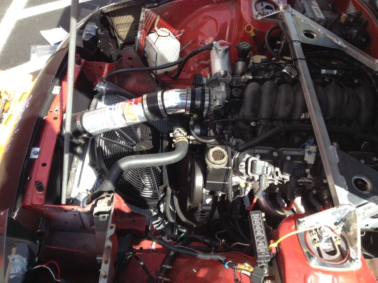
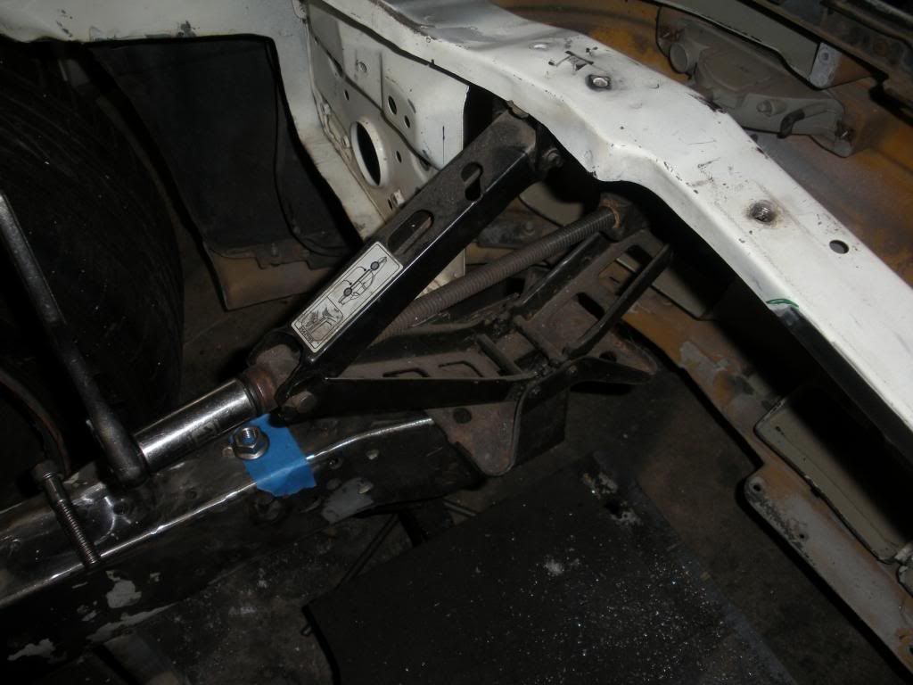
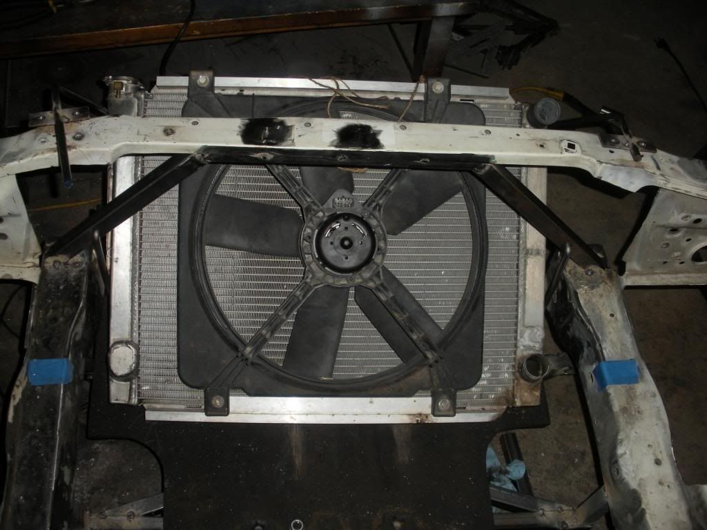
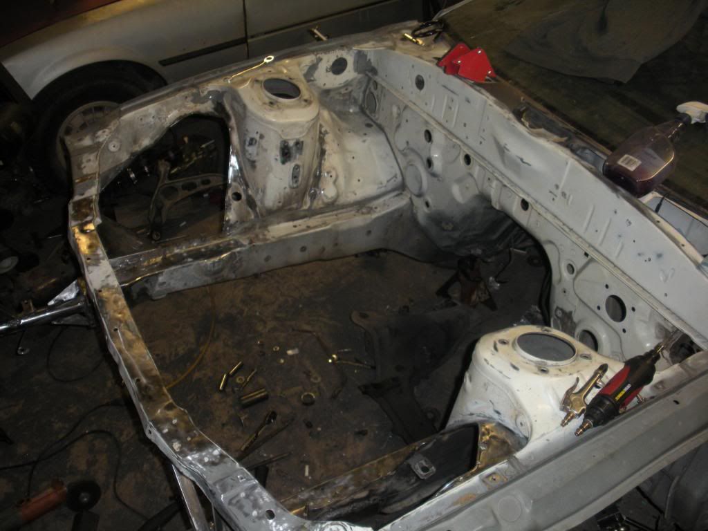
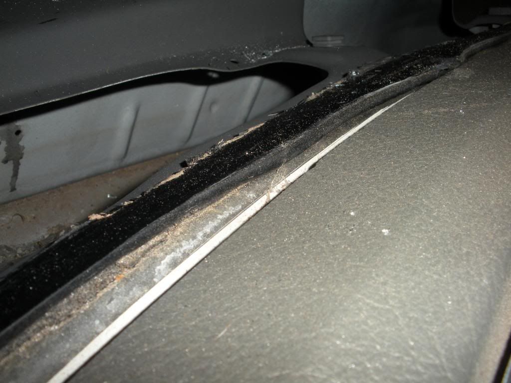
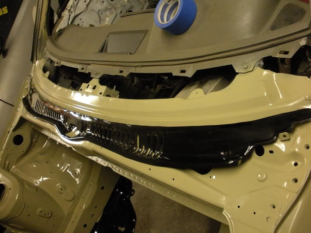
Lastly there's how the radiator will be approx. Basically it has to stay behind the blue tape marks (Measured off of Big Josh's car in the pictures above) and under the radiator support. To be sure it clears the main pulley on the engine and the hood at the top / front. It will be a bit lower and more angled of course. it's just leaning on the bumper for the picture since I had yet to make something to actually hold it up.


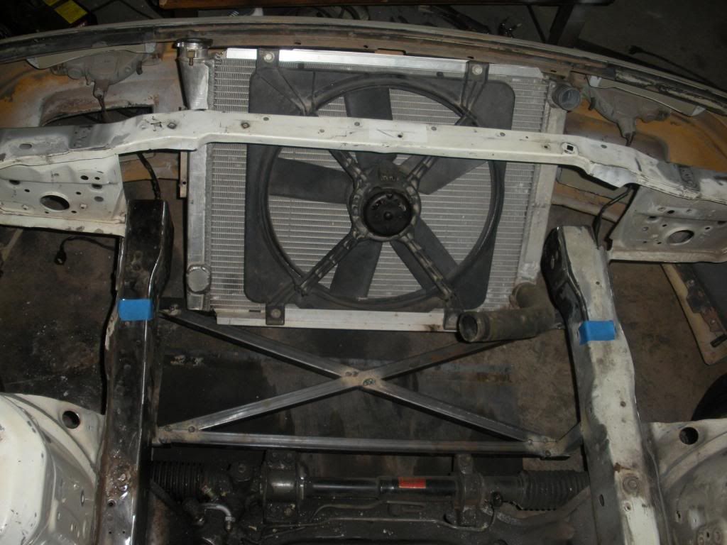
I'll be trying to get the radiator mount stuff sorted today. But I need to run to the junkyard and measure some Camaro intakes and such to see what I have for clearance between the top of the engine and hood. Luckily we just put my factory hood on Josh's car a couple days ago so I have measurements from his for maximum height and all that.

I've decided this thing is going to be fuel injected. Now to decide which intake to use. The TPI one, or LT style, or Holley aftermarket, or Edelbrock aftermarket one. They reallly all come out about teh same in cost in the end, So it's more a matter of powerband and fitment really.

Here's a pretty cool page I found of some pretty decent testing on a 383 SBC:

http://xtremecarzone.com.au/index.php?showtopic=386
StephenSheppard is offline   Reply With Quote
Old 11-19-2012, 09:55 AM   #23
Raksj04
I have Ultra power in me.
 
Raksj04's Avatar
 
Join Date: Sep 2011
iTrader: (2)
Posts: 457
Rep Power: 13
Raksj04 is on a distinguished road
Default


I hope you tirmed the bolts down. Those could give you some nasty punctor wounds if you don't.
Raksj04 is offline   Reply With Quote
Old 11-21-2012, 09:30 AM   #24
StephenSheppard
Rotary Fan in Training
 
Join Date: Nov 2012
iTrader: (0)
Posts: 58
Rep Power: 12
StephenSheppard is on a distinguished road
Default

LOL everyone is always worried about that. I'm not sure who is actually tall enough for their head to touch the outer skin of the roof and still have the ability to fit in the car. Don't worry it's taken care of already man.


Also a bit of this happened the other day. There was a bit a cracking and popping but the radiator support is back to it's original height on that side now.

StephenSheppard is offline   Reply With Quote
Old 12-11-2012, 11:35 AM   #25
StephenSheppard
Rotary Fan in Training
 
Join Date: Nov 2012
iTrader: (0)
Posts: 58
Rep Power: 12
StephenSheppard is on a distinguished road
Default

Haven't updated in awhile due to breaking my hand with a drill. yep a drill. It was super fun........

Basically my hand met a drill body that was spinning really fast and broke some of those little bones behind the knuckles. Hurt like hell was swollen up pretty good as well. Also i started a new job and that's borrowing a lot of my time lately.

I'll get back on this pretty quick though, my hand is nearly operational now.
StephenSheppard is offline   Reply With Quote
Old 02-25-2013, 12:58 AM   #26
StephenSheppard
Rotary Fan in Training
 
Join Date: Nov 2012
iTrader: (0)
Posts: 58
Rep Power: 12
StephenSheppard is on a distinguished road
Default

Soooooooooooooo........

Ya I forgot to update this thread.......like a lot.

Let me try to figure out how this was going.


I started mocking up the radiator brackets. These were unfinished parts of course I was just trying to get some sort of direction on what I liked. Turns out I didn't like any of it lol. Here's some pics anyways.


I messed with that for a couple days and couldn't get any kind of setup that was stable enough or would keep vibrations down to something I felt was appropriate for an aluminium jam bouncing around in the front of the car.

So I ignored the problem hoping it would go away or whatever lol, and moved on to finishing up the x-brace for the bottom of the front of the car.


I painted it and all that on my FB hood cause why not right? Later that turned out to be a waste of time and I had it powdercoated black with a bunch of other stuff.


Then I moved on to cut and notch the outside of the frame rails where that annoying little tab of metal sticks out that everyone beats in with a hammer to gain tire clearance.


I welded in some steel. Kind of bootleg but whatever.


I can't really remember what I did next so I'm guessing, but anyways at some point I modified the pedal assembly for the new Wilwood clutch master cylinder that comes with the Granny's Speed Shop SBC kit.


Basically I figured the alignment of the MC bolts and welded on tubing to support the firewall at the new hole locations. Copying the factory setup seemed like the thing to do. I just used a slightly larger size of tubing since it's not critical or anything.


StephenSheppard is offline   Reply With Quote
Old 02-25-2013, 01:05 AM   #27
StephenSheppard
Rotary Fan in Training
 
Join Date: Nov 2012
iTrader: (0)
Posts: 58
Rep Power: 12
StephenSheppard is on a distinguished road
Default

The next pic in the camera was this, but it jumps past some other stuff. I guess I forgot to take some pics, get over it I guess.


You can see the radiator bracket changed quite a bit. Still had the bent rod passing through the diagonal square tubes at this point. That was again revised. I have heard you never dead head pipe into a frame rail......so I did that first thing as my approach to extending the frame rails lol......oops. Well I did leave some other stuff welded less so it can crush. We will come back to that. Added the mount tabs for the radiator bracket to the round frame extensions. The radiator is just hanging there in the pic trapped not actually mounted in any way.

Got this stuff powdercoated.

StephenSheppard is offline   Reply With Quote
Old 02-25-2013, 01:19 AM   #28
StephenSheppard
Rotary Fan in Training
 
Join Date: Nov 2012
iTrader: (0)
Posts: 58
Rep Power: 12
StephenSheppard is on a distinguished road
Default

Added some round stock to the inside edge of the fender well holes since I'm leaving the hole open and I don't feel like getting cut everytime I touch any of that.


Had the subframe powdercoated.


Pretty sure this is the pic just before I started prepping the engien bay for paint. Took everything off the chassis, then sanded, and sanded, and wire wheeled and basically it took forever since I can't dedicate huge amounts of time to teh car all at once. You can see there was a couple improvements made to the frame rail extensions.


Seam sealer and some primer happened.


Bought a couple hundred dollars of stainless steel 3/16" tubing and fittings for the brake system. Bought more later lol.


Bought an ASD hydro E-brake


Cut my broken windshield out and finished primering the engine bay.


This stuff comes off super easy with a razor blade and then a soft wirewheel in a drill.


No windshield status

StephenSheppard is offline   Reply With Quote
Old 02-25-2013, 01:33 AM   #29
StephenSheppard
Rotary Fan in Training
 
Join Date: Nov 2012
iTrader: (0)
Posts: 58
Rep Power: 12
StephenSheppard is on a distinguished road
Default

Then we skip ahead in time again.

And........................................

Painted.


Paint came out pretty nice. I dig it. The whole car will be painted that color when it's all said and done.

One the "bumper" I tried to stay away from doing too much heavy welding in hopes that this stuff will be destroyed in case of a say 20mph or more impact. hopefully it's a sound thought process. Also hopefully I never find out. To be realistic it is a drift car so the coolers will probably be destroyed in a decent speed collision.

Painted the wheelwells also. They will get all scratched up of course but figured it could start by looking decent and then I won't care about what happens later really.


Installed the subframe

StephenSheppard is offline   Reply With Quote
Old 02-25-2013, 01:47 AM   #30
StephenSheppard
Rotary Fan in Training
 
Join Date: Nov 2012
iTrader: (0)
Posts: 58
Rep Power: 12
StephenSheppard is on a distinguished road
Default

Something happened here


More stuff goes to be powdercoated. The x-brace, the radiator bracket (revised for the third time), the slave cylinder mount, the steering rack brackets, the front LCA brackets, the engine cradle, and the trans bracket. Maybe some other stuff I don't know it's hard to keep track off honestly.


A neat picture with tubing nuts and sleeves lol


Painted the brake booster and loosely mounted it and the brake master cylinder. Began the process of building the MC lines to the firewall bulkheads. The proportioning valve will be inside the car. One problem with the FC factory MC is that it has two front outputs right off the MC. I had to buy a plug for one of the outputs so that there would be just the one. The fronts brakes divide after the proportioning valve now, more on that later.


Built the front brake lines up to teh bulkheads in the firewall as well. almost a finished product at this point.


I didn't like how the rear MC brake line was laying out so I started over lol.


Front line is on the right in the picture at the firewall.


Here's what's in the wheelwells. I used a staright -3AN bulkhead and bolted that through the brake line holder. All the brake stuff is now -3AN no more inverted flare stuff or any of that. Doing 37 degree flares is far faster and easier then doing double 45 degree flares, plus it looks cooler. I chose steel stuff due to the fact that is far more resilient than aluminium stuff. I don't need a brake line failure because a little rock popped a hole in something. Also the stainless stuff weighs such a small amount more it's not even worth mentioning really.

StephenSheppard is offline   Reply With Quote
Reply

Bookmarks


Posting Rules
You may not post new threads
You may not post replies
You may not post attachments
You may not edit your posts

BB code is On
Smilies are On
[IMG] code is On
HTML code is Off

Forum Jump


All times are GMT -5. The time now is 11:27 AM.


Powered by vBulletin® Version 3.8.4
Copyright ©2000 - 2024, Jelsoft Enterprises Ltd.
Hosted by www.GotPlacement.com
Ad Management by RedTyger