Quote:
Originally Posted by j9fd3s

neat thread! i've not much to contribute except that i've read a lot of SAE papers and Mazda has published a lot of rotary specific info.
particularly 831010 which is the 6 port intake system. the 90032 rotary P port modeling paper. also the S2000 paper is good, although isn't rotary specific. there is an S5 paper too.
the crib notes, we know about the lengths, i think, shorter = higher rpm peak.
they have a graph of plenum size vs VE, and due to the 270 degree cycles the rotary has what they call a tournament effect, when one rotor closes it uses the reflection to charge the other rotor. Mazda found a smaller plenum increases this effect. honda actually found the same, which is why the S2000 has a teeny plenum.
with the Rx8, all the runners (primary, secondary, thirdinary, corollary, arbitrary, and fred), have tuned lengths AND diameters.
from the info provided it really looks like Mazda made something that they could easily change the lengths on, and then they just tried a bunch, easier to do on a P port.
mike
|
Which makes sense if you consider the Helmholtz equation. By varying the diameter of the runners you automatically affect the various lengths required to capture the waves. Shrinking the plenum would in fact magnify the effect, but that effect is, in part, only appreciable at certain RPM unless you do adjusting length runners (similar to how the VDI system on the s5 worked if I remember correctly).
I have done some work on the Helmholtz equation, but nothing I feel comfortable sharing quite yet. Especially since wave harmonics would play a significant role in the length.
Quote:
Originally Posted by ninesixtwo
Good thread and nice work, lots of good info in here. Just a thought though, why haven't you been running your simulations with timed port openings? My brother did some similar work when designing an intake manifold for a V6. He started off modeling airflow with all valves open. The initial simulations yielded what seemed to be horrible airflow distribution:
 |
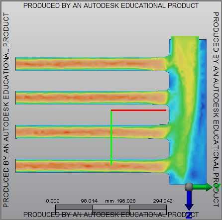
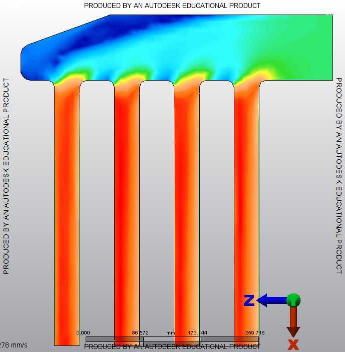
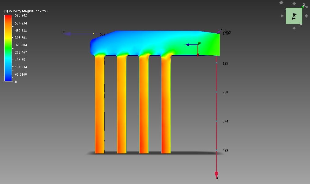
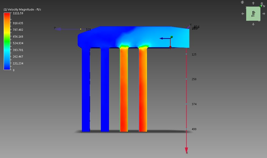
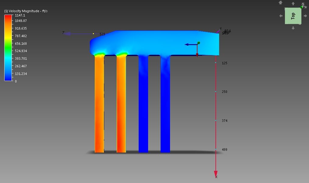
There's a few reasons for that. The program I was using didn't readily allow me to do timed/moving components very easily. However, I have finally gotten the new CFD program up and running and seems to be handling the constraints much easier. I will eventually simulate the opening and closing of the various ports, but I probably won't fool around with the transient nature of doing it dynamically. Right now I'm doing flow and pressure simulation and have found that by varying the exit pressure from the simulation causes a peculiar velocity distribution to appear in the runners. I'll post pictures later on this week (hopefully).
Quote:
But before we started making changes to his plenum, we decided it would be best to model the flow in as correct a manner as possible. It took a lot more work to get the time-based model working correctly, but the end results were pretty surprising. The simulation looked to be much more promising, but still not perfect - until we looked at the data from the analysis instead of the visual simulation. All runners received within 0.1% mass air volume!
http://www.youtube.com/watch?v=EpJ4x...ature=youtu.be
|
The flow distribution on the standard manifold was terrible and closing the ports would not have solved the issue. The air pretty much 'skipped' the inboard runners and hitting the primary runners only. Closing one half of the runners for the simulation would not have solved this problem. I'll try to reply and update later on this week, but it all depends on what's going on. Hopefully I'll have some more insight/better thought out sentences to explain.
Quote:
Originally Posted by Pettersen
What about TB placement.
From what i can find, it seems like overall runner length is the main point, and the placement of the tb isn't too important when it comes to where your powerband ends up.
|
TB placement is a rather complicated issue. Depending on where you put it relative to the runners in both direction and magnitude affects the plenum volume. The design I'm working on/refining sort of takes the throttle body out of the equation at the moment, but I imagine I will be doing motion simulation with the CFD to see how it affects the air flow at partial throttle. Depending on how you implement the throttle body, plenum, and runners; your throttle response, pressure distribution, sensor locations, and even fuel atomization will be affected. That's not to say that a box and runners with a 90mm throttle body won't work, but it also means you might starve a rotor too.


 Linear Mode

