|
|
 07-10-2010, 08:50 AM
|
#1 |
|
Rotary Masochist
Join Date: May 2008
Location: Floyds Knobs, IN
Posts: 494
Rep Power: 18  |
Why are you guys assuming Barry is only using one spark plug per rotor?

__________________
_______________________________________________ One stop Haltech, AEM, Syvecs shopping. Installation and tuning. http://www.lms-efi.com Free support. Drop us an email. chris@lms-efi.com 502-515-7482 Facebook @LMS-EFI |

|

|
|
07-10-2010, 09:47 AM
|
#2 | |
|
Don Mega

Join Date: Dec 2008
Location: Utopia
Posts: 1,688
Rep Power: 18 |
Quote:
 I looked into it a long time ago, still have quotes probably on it. I looked into it a long time ago, still have quotes probably on it.
__________________
www.riceracing.com.au Worlds best Apex Seals Coil on Plug Water Injection ECU Calibration |
|
|
|
|
|
07-10-2010, 10:16 PM
|
#3 | |
|
Rotary Masochist
Join Date: May 2008
Location: Floyds Knobs, IN
Posts: 494
Rep Power: 18 |
Quote:
I was simply pointing out the error in thinking that only one plug per rotor was being used.
__________________
_______________________________________________ One stop Haltech, AEM, Syvecs shopping. Installation and tuning. http://www.lms-efi.com Free support. Drop us an email. chris@lms-efi.com 502-515-7482 Facebook @LMS-EFI Last edited by Barry Bordes; 07-11-2010 at 08:05 AM. Reason: Non scientific addition. |
|
|
|
|
|
07-11-2010, 12:32 AM
|
#4 | |
|
Don Mega
Join Date: Dec 2008
Location: Utopia
Posts: 1,688
Rep Power: 18 |
Quote:
I will discuss with Barry.
__________________
www.riceracing.com.au Worlds best Apex Seals Coil on Plug Water Injection ECU Calibration Last edited by Barry Bordes; 07-11-2010 at 08:07 AM. Reason: Non scientific addition. |
|
|
|
|
|
07-11-2010, 07:53 PM
|
#5 |
|
The quest for more torque

Join Date: Sep 2008
Location: Sheboygan, Wisconsin
Posts: 855
Rep Power: 18 |
Sorry about the confusion, I thought the same thing that others did, this was a simple transducer installed in the leading spark plug hole.
From what I have seen, there is more available power by building that peak pressure earlier in the cycle. If you are seeing detonation with earlier pressure peaks, 45 degrees is what you get. (This really isn't too bad, at is equates to 30 degrees on a piston engine. As I recall, 12-15 degrees is the sweet spot for peak cycle efficiency (on a piston engine). The rotary may be different. Actually, now that I think about it, the rotary has a longer combustion chamber and probably requires longer for the flame to propagate. This may mean that the pressure will spike too quickly is it is initiated any sooner, while taking too long to propagate if initiated at this time. Anyway, I hope that you are planning to analyze the effects of leading/trailing split. Some claim that it makes a big difference, I found no change on the dyno at all for pretty much the entire test. In fact, I unplugged the trailing plugs and saw no change under 6,000 rpm.
__________________
1986 GXL ('87 4-port NA - Haltech E8, LS2 Coils. Defined Autoworks Headers, Dual 2.5" Exhaust (Dual Superflow, dBX mufflers) 1991 Coupe (KYB AGX Shocks, Eibach lowering springs, RB exhaust, Stock and Automatic) |
|
|
|
|
07-12-2010, 07:13 AM
|
#6 | |
|
Rotary Fanatic

Join Date: Feb 2008
Location: Slidell, LA
Posts: 191
Rep Power: 18 |
Quote:
There are a lot of concepts to interrelate when considering what is going on inside of a rotary engine. This is from a Mazda paper Rotary86v6a4, Fig. 14, showing flame propagation. I think this is probably Mazda Research at its best! If you haven't seen it before please take your time trying to understand it. 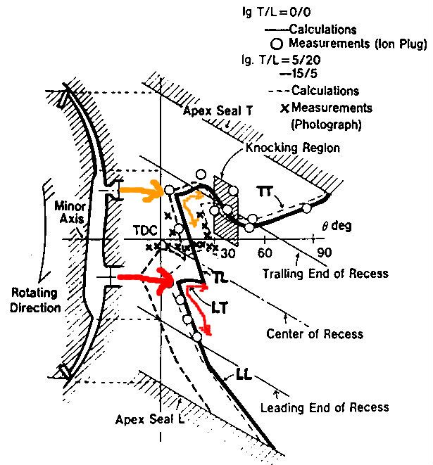 Some things to note: Because the mixture is flowing the flame front hardly moves upstream at all. In fact the trailing portions of both flame patches are pushed backwards part of the time. The squish generation and trench shape further complicates this movement. When the leading and trailing flame fronts collide (at about 20º ATDC) that their speed diminishes. The knock region is from 30º - 45º ATDC and where the knock sensor is located. Barry |
|
|
|
|
|
07-12-2010, 05:36 AM
|
#7 |
|
RCC Loves Me Not You

Join Date: Jul 2008
Location: Influx.
Posts: 2,113
Rep Power: 20 |
Barry do you know your %error on the calculations at all?
__________________
The Official FC Radiator Thread My Project Thread: Cerberus CCVT Virginia Rotary Group |
|
|
|
|
07-12-2010, 09:40 AM
|
#8 | |
|
Rotary Fanatic
Join Date: Feb 2008
Location: Slidell, LA
Posts: 191
Rep Power: 18 |
Quote:
The timing trigger that I fabricated adjacent to Mazdas timing wheel would be the area for greatest possible error. To check this a test run is then made where the engine ignition is cut at 6000 rpm and the throttle is opened fully. This double-checks TDC in relation to the logged actual compression hump. To my knowledge the rest are calculations. 
|
|
|
|
|
|
07-14-2010, 10:17 AM
|
#9 | |
|
RCC Loves Me Not You
Join Date: Jul 2008
Location: Influx.
Posts: 2,113
Rep Power: 20 |
Quote:
If you know the calculations they're running for any given reading you can easily perturb the uncertainties to get a culmulative percentage of error. That way you can at least know the accuracy of your results. From my glances you could be on the mark or you could be slightly off. Without the error it's hard to gage application to different stress/repeatabilty.
__________________
The Official FC Radiator Thread My Project Thread: Cerberus CCVT Virginia Rotary Group |
|
|
|
|
|
07-14-2010, 05:27 PM
|
#10 | |
|
Rotary Fanatic
Join Date: Feb 2008
Location: Slidell, LA
Posts: 191
Rep Power: 18 |
Quote:
For aircraft testing instrumentation we had to recertify sometimes every six months. I don't want to certify different dynos for the FAA or DOT. I want it to be accurate but I will pass on recertification. Really I just want to know is this log an improvement or have I gone too far! I am using it just like our Datalogit tuning for AFR, transition, etc. http://www.optrand.com/Papers/fisita98/fisita98.htm Barry Last edited by Barry Bordes; 07-14-2010 at 05:54 PM. |
|
|
|
|
|
07-12-2010, 09:20 PM
|
#11 |
|
The quest for more torque
Join Date: Sep 2008
Location: Sheboygan, Wisconsin
Posts: 855
Rep Power: 18 |
Correct me if I am completely mistaken, I will try to explain the figure.
The diagonal lines indicate the position of each component as the rotor rotates. The angle indications are in rotor degrees, not eccentric shaft degrees. The distance from the left indicates degrees of rotation when that region of the chamber burned. The different lines are the different ignition timing settings that clearly cause significantly different behavior. The trailing side seems to be the weird one, the flame front displacement seems to shift nicely for all points below the leading plug. It looks like the flame front is traveling forward just fine, it is the backward part of the curve that confuses me. This would seem to indicate the the flame front follows the rotor rather than the housing (which makes sense, the rotor has the dish). I think I see why it knocks right above the trailing plug, the flame front actually reverses direction there (although not relative to the rotor). This must be right at the quench boundary at the edge of the rotor dish (probably when it meets the cusp on the housing). Do you know what the engine speed was for this test? Do you know the manifold pressure? (I would guess NA). It appears that at 20 BTDC, the leading front has basically dissipated by 45 degrees (Eccentric shaft, 15 rotor) (which makes sense why you observed the highest pressures when the peak occured at 45 degrees) Here is a theory about what is causing your knock on too much timing advance. Knock is typically caused by some shock wave colliding with the flame front (it can be a second flame front). My thought is that the leading and trailing sparks both touch off the mix in the chamber if the timing is advanced too far, this results in the two flame fronts colliding while they are stil moving very quickly. To test this, you could try unplugging the trailing plugs or adjusting the ignition split and observing what difference it makes. This research is awesome. Where did you find that diagram?
__________________
1986 GXL ('87 4-port NA - Haltech E8, LS2 Coils. Defined Autoworks Headers, Dual 2.5" Exhaust (Dual Superflow, dBX mufflers) 1991 Coupe (KYB AGX Shocks, Eibach lowering springs, RB exhaust, Stock and Automatic) |
|
|
|
|
07-13-2010, 09:32 AM
|
#12 | |
|
Rotary Fanatic
Join Date: Feb 2008
Location: Slidell, LA
Posts: 191
Rep Power: 18 |
Quote:
Barry |
|
|
|
|
|
07-13-2010, 10:11 PM
|
#13 |
|
The quest for more torque
Join Date: Sep 2008
Location: Sheboygan, Wisconsin
Posts: 855
Rep Power: 18 |
Shaft degrees makes more sense in the diagram (the rotor would have moved quit a bit further at 90 degrees). I think I was second guessing myself.
The reason I consider the ignition event to be at 20 BTDC is that there is observeable flame front propagation before 0 degrees, which excludes the ATDC option. It is strange that they neglect to indicate ATDC or BTDC. I saw the reference earlier, I meant where did you find the paper? Is that an SAE paper? This explains what I saw in several articles about trailing plug positioning, that further up the housing (rotor clears it earlier) is preferred for peak power. edit: It would be really awesome to see what the flame front does at 7,000 rpm....
__________________
1986 GXL ('87 4-port NA - Haltech E8, LS2 Coils. Defined Autoworks Headers, Dual 2.5" Exhaust (Dual Superflow, dBX mufflers) 1991 Coupe (KYB AGX Shocks, Eibach lowering springs, RB exhaust, Stock and Automatic) Last edited by NoDOHC; 07-13-2010 at 10:14 PM. |
|
|
|
|
07-14-2010, 07:00 PM
|
#14 |
|
RCC Loves Me Not You
Join Date: Jul 2008
Location: Influx.
Posts: 2,113
Rep Power: 20 |
Oh believe me I know about samples and windowing. It's annoying as crap
 Hence why I asked the question. Hence why I asked the question.As for the 3 million/min... why do you make me do math? I hate math! so you'd be sampling at 48khz unless you wish to avoid windowing then you'd need to sample at 96khz. Is the timing sensor hall or optical? (I'm trying to estimate the sensor error to guesstimate the perturbed error) so your calibration uncertainty is 0.04% which ain't bad. If you can nail down the timing uncertainty it will be easy enough to get an uncertainty plot for the pressure distribution.
__________________
The Official FC Radiator Thread My Project Thread: Cerberus CCVT Virginia Rotary Group |
|
|
|
|
07-15-2010, 02:10 PM
|
#15 | |
|
Rotary Fanatic
Join Date: Feb 2008
Location: Slidell, LA
Posts: 191
Rep Power: 18 |
Quote:
|
|
|
|
|
 |
| Bookmarks |
| Tags |
| barry bordes, bmep, imep, in chamber, pressure sensors, tfx |
|
|


 Hybrid Mode
