|
|||||||


| Show your rotary car build up. Show off your Rotary Car build! |
 |
|
|
Thread Tools | Display Modes |
|
|||||||
| Show your rotary car build up. Show off your Rotary Car build! |
|
|
|
Thread Tools | Display Modes |
 04-04-2008, 06:43 PM
|
#1 |
|
The Newbie
Join Date: Apr 2008
Posts: 11
Rep Power: 0  |
My 87 TII Build!
My RX-7 Build
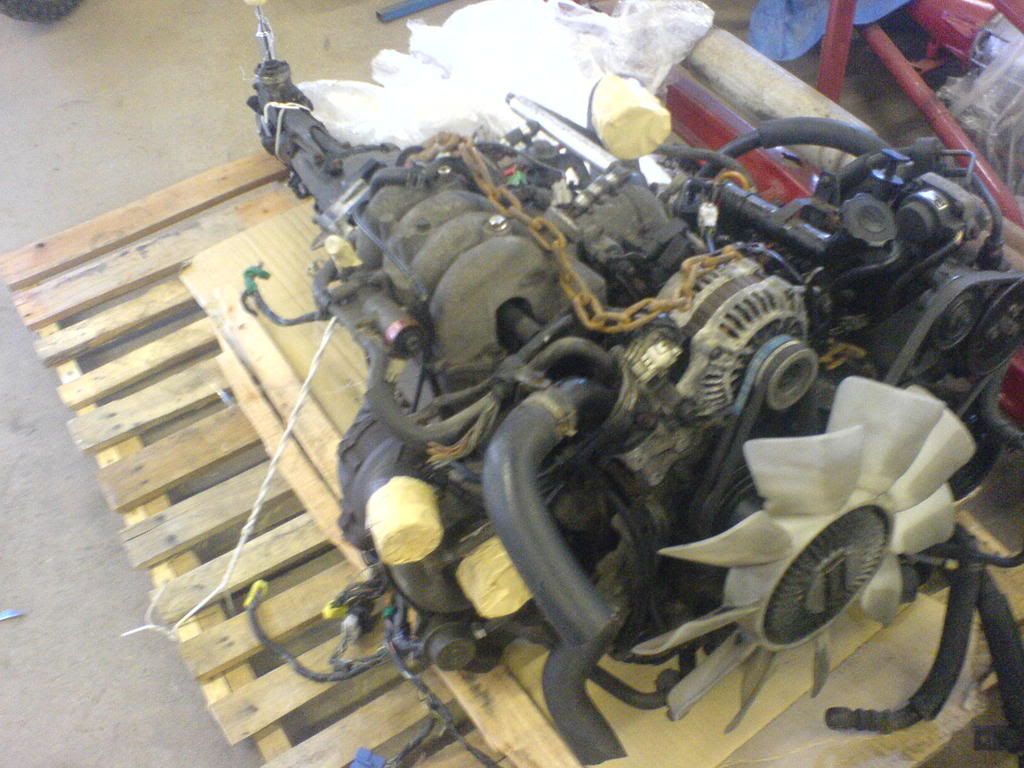
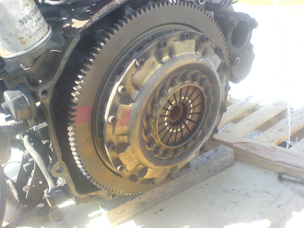
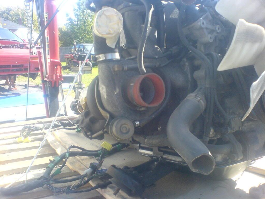
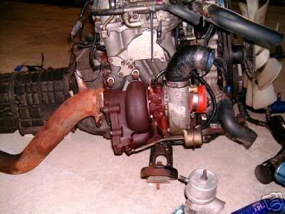
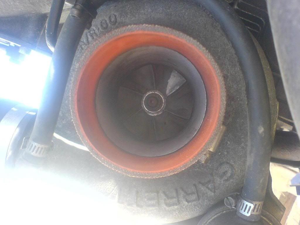
I started with a 1987 RX-7 TurboII Chassis with original 140k kms on it, the body is solid, theres no rust whatsoever on it, although it was pretty dirty under the hood, and the red hood ended up getting damaged so it has a black TII hood on it right now. Here are some pictures of the car when I first got it. 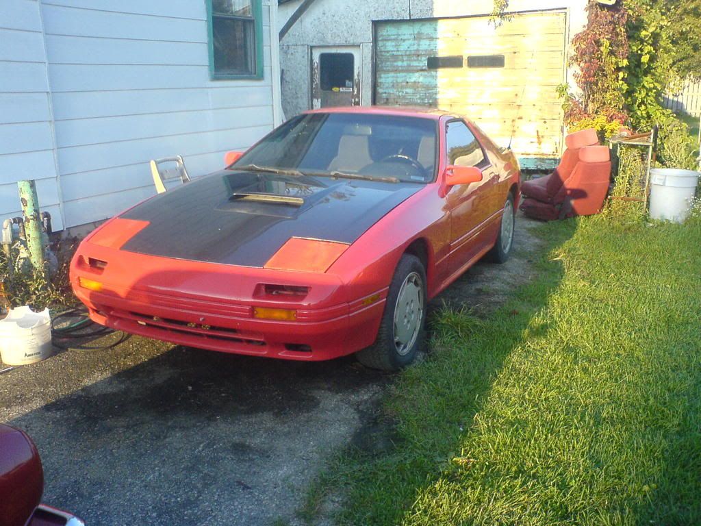 The Engine Bay 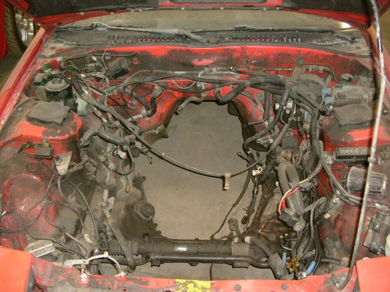 As you could see the engine bay was pretty Grimy when I got the car, everything was covered by a thick greasy sludge. Im not a big fan of the spray on engine bay cleaner .Dawn dish soap and time works a lot better in my opinion, and its not harmful to your paint and driveway. It probably took a good 4-5 hours of scrubbing to get the engine bay to this point 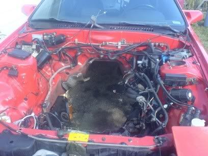 After I finished the engine bay I switched out the headlight covers and the sunroof panel from my parts car because the ones on this car must have been switched before I bought it because they were pretty rough and the sunroof panel had the usual rust Thats all Ive done to the body so far I just wanted to minimize any rusting during the winter time. because its going to be sitting in a driveway till spring The Motor After I finished off getting the chassis cleaned up I started prepping the engine for the swap. I got a killer deal on this engine its a JDM S5 13B-T built and tuned by Toms Racing in Japan. Total I paid $2600 for the engine, Trans and a bunch of goodies What the engine came with: JDM S5 13b-t 5-speed transmission N374 toms racing ecu Garrett a/r.60 with t70 wheel, hybrid turbo 2x 550cc injectors in dynamic chamber Dual alternator belts OS Giken Twin disc clutch and Lightweight flywheel Old school greddy intercooler piping with greddy elbow 2x 550cc injectors in the IC piping Greddy Big Type-R BOV 3 downpipe Apexi Series 5 airfilter and AFM |

|

|
|
04-04-2008, 06:48 PM
|
#2 |
|
The Newbie
Join Date: Apr 2008
Posts: 11
Rep Power: 0 |
motor pics
|
|
|
|
|
04-04-2008, 06:52 PM
|
#3 |
|
The Newbie
Join Date: Apr 2008
Posts: 11
Rep Power: 0 |
Chassis harness prep
To get the motor to work in the Series 4 Chassis I had to splice together the 2 engine harnesses. Luckily my engine came with the S5 chassis harness to ECU plug So I spliced the series 5 end onto the series 4 chassis harness, theres 4 wires that need to go to the #2 ecu plug, this is where a parts car comes in handy, I found a male and female connector with the same gauge wires and used that so I can easily disconnect those wires in the future. I also had to use the Series 4 Crank Position Sensor wires and ran those to the series 5 engine harness, I just found another male and female connector for those. Altogether I have 7 wires that needed to be spliced to the series 5 engine harness 3 Crank Position Sensor wires, battery, ignition switch, main relay, fuel pump resistor Relay. I have a 4 wire connector and a 3 wire connector and a S5 chassis harness to ecu plug spliced on the end of the S4 chassis harness I did it one wire at a time so I made sure I didnt mix any up, get some shrink wrap and solder each wire so theres no chance of a short later on down the road. There are a few pins that werent needed for actual engine function they are just auxiliary items such as fog lights, rear defroster ect So I didnt even bother connecting those, a couple of them had the pin totally removed. When all this was done the Chassis was ready for the S5 swap and I moved onto the engine harness Engine harness prep I started out with a Series 4 and Series 5 engine harness; I completely stripped the S4 harness. The FEM connector with all the wiper motor connectors on it. Is actually only connected to engine harness by 2 wires, a ground and a wire to some solenoid, the other FEM connector I traced the wires through the engine harness, the wires are mostly grounds, the oil pressure sensor and the water temperature sensor and the one wire tied into the boost sensor wire goes to the stock boost gauge . the 3 wires for the ignition switch, battery, and fuel resistor relay come out from the 2nd FEM connector and originally went to the s4 #2 ecu plug but I hooked them up to the female end of the connector I spliced on the #1 S5 ecu to chassis plug When I had the 2 FEM plugs separated from the Series 4 harness I moved onto the series 5 engine harness I stripped the series 5 harness from the ecu plugs to where it started to branch off to all the sensors. I used a JDM RHD engine harness so it was a little different there is only one FEM connector. The actual colour combination is very similar on the S5 harness. for the grounds were the same brown wires so I just spliced in grounds from the S4 FEM plugs to where the S5 fem plug grounds were, I Had to run the 3 wires from the #2 ECU plug for the CPS wires and spliced them on a 3 wire connector. Connected the boost gauge wire and my stock gauge works! It was mostly just grounds that I spliced in from the S4 FEM to S5 engine harness, and where it branches off the boost sensor. I had to splice into the black with white stripe wires that go through the engine harness to the 4th wire on the connector I added for the MAIN RELAY. I just left the connectors for the wipers and cruise alone. I measured to see where the FEM plugs needed to sit on the harness and got some heat resistant electrical tape .I dont know if its just because Im Canadian lol but I like to wrap the harness with a layer of hockey tape before I wrap it I figure It adds a bit of durability to the harness. I rewrapped the harness all nice, and in the end I ended up with a S5 engine harness with 2 S4 FEM plugs, a 4 wire connector for the ignition switch, battery, main relay, FR relay, and a 3 wire connector with the CPS wires I hooked it back up on the engine as it normally sat on the engine as a RHD harness but I ran the wiring along the back fire wall and in the end turned out to be a good way to do a wire tuck .you can basically only see the connectors that are normally visual .but the rest of the engine harness is hidden. I have the ecu in the normal mounting bracket. S4 to S5 changes I had a hard time trying to find what I was going to have to change when I did my swap. All Experts like to pretend they know everything but it was quite obvious they didnt have a clue. The Series 5 TII transmission cradle and crossmember are different I found that out after I bought a series 4 crossmember. I ended up buying them new from the Mazda dealer. I had to also get a N370 pressure sensor, and the I have to get a S5 style koyo rad with the filler neck on the rad. For now Ive been using a remote filler neck, does the trick. Altogether the changes I made to the wiring harness and the Trans crossmember, pressure sensor, and radiator those are the only changes I had to make to get my JDM Series 5 TII engine to run in my 87 TII. Here's a picture of the engine after I put it in  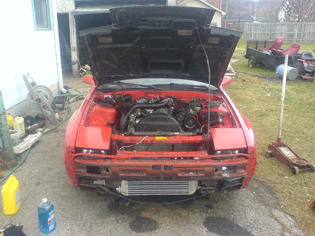 Coming Soon Walbro 255lph fuel pump 3 Stainless Steel Turbo back exhaust MS1 v3 Coilovers with camber plates Mazdatrix Steering angle kit Energy Suspension bushing kit HD ball joints Bodykit Lightweight black 17 rims Fresh Red Paint EBC green brake pads Slotted rotors SS brake lines SS clutch line S5 Tail lights Polyurethane engine, Trans, diff mounts Rear steer eliminator Front and rear Strut bars Thats what I hope to have done by the end of the season! |
|
|
|
|
04-04-2008, 06:55 PM
|
#4 |
|
The Newbie
Join Date: Apr 2008
Posts: 11
Rep Power: 0 |
The car should be on the end of April , and the megasquirt should be in hopefully the first week of may
heres a video of it running so far http://www.youtube.com/watch?v=voB4tEXOoqE let me know what you guys think so far!!! i'm goin to work on it this weekend its sappose to be nice and sunny so i should get alot done, i'll post more of what i do as i go 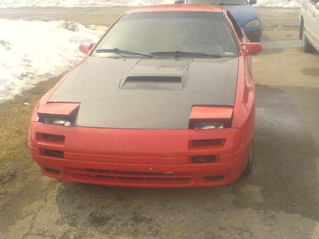
Last edited by FC3SDrift; 04-04-2008 at 07:07 PM. |
|
|
|
|
04-05-2008, 11:39 PM
|
#5 | |
|
rotors excite me

Join Date: Mar 2008
Location: Iowa
Posts: 372
Rep Power: 18 |
hahaha, it sounds a lot like mine does when I pull the midpipe off. And no matter what I get the hesitant fall in RPM on decel. Looks like you're making good progress!
__________________
He isn't a killer. He just wins -- thoroughly.   '87 TII 240+ rwhp on my DIY streetport, ~13psi on stock turbo, Racing Beat REVTII exhaust  rTek 2.1 awaits a tune Quote:
|
|
|
|
|
|
| Bookmarks |
| Thread Tools | |
| Display Modes | |
|
|


 Linear Mode

