|
|||||||


| RX-7 3rd Gen Specific (1993-2002) RX-7 1993-2002 Discussion including performance modifications and Technical Support Sections. |
 |
|
|
Thread Tools | Display Modes |
|
|||||||
| RX-7 3rd Gen Specific (1993-2002) RX-7 1993-2002 Discussion including performance modifications and Technical Support Sections. |
|
|
|
Thread Tools | Display Modes |
|
|
 06-16-2009, 03:48 PM
|
#1 |
|
Rotary Fanatic
Join Date: Mar 2008
Posts: 162
Rep Power: 18  |
Ignition re-wire...shielded wires?
I'm in the middle of performing the ignition re-wire that Chuck has brought up before. If you are not familiar with the procedure, it is basically shortening the wires from the ignition module in the driver's side corner of the engine bay, to go directly to the coils eliminating some length of wire. There are 3 wires that go from the module to each coil, as well as a power wire. The 3 wires are shielded together. Would this product be appropriate to wrap the wires with after I solder in a length of new wire?
http://www.mcmaster.com/#sleeving/=2cgecb Or does each wire need to be shielded individually to prevent interference from each wire? And the power wire goes to the ignition module, and the same wire also goes to each coil. Since I want to eliminate the connector all together, could i tap into the power wire at the module and run it to the coils? |

|

|
|
06-16-2009, 06:37 PM
|
#2 |
|
Rotorhead
Join Date: May 2008
Location: Drumheller, Alberta
Posts: 164
Rep Power: 18 |
The metal sleeving may work as shielding, as long as you somehow made provisions to ground the sleeving (which is the key to proper shielding.)
You could also look more into this product: http://www.acsindustries.com/product...e/default.html Or best (and easiest) option: Get yourself some shielded 3 wire Belden Cable from your local or nearest electrical wholesaler (or online). Then you don't have to wrap anything.
__________________
 ||| Never argue with idiots. They will bring you down to their level and beat you with experience. ||| |
|
|
|
|
06-16-2009, 08:42 PM
|
#3 |
|
The Newbie

Join Date: Apr 2009
Posts: 18
Rep Power: 0 |
What is the advantage to doing this?
Is this done to help clean up the engine bay? |
|
|
|
|
06-16-2009, 11:21 PM
|
#4 | |
|
Rotary Fanatic
Join Date: Mar 2008
Posts: 162
Rep Power: 18 |
Quote:
"No, but you can greatly reduce all RFI. Did you know that Mazda made another serious desgin flaw with their ignition wiring? It can be easily fixed and the result is hotter sparks even with stock ignition. The ECU on the pasenger side, fires the ignitior on the driver side. OK we will accept this approximate 6' of wiring. But instead of running the ignitor to coil wires directly to the coils which are about 18" away, they wired them back over to the chassis harness by the ECU, out to the harness that goes to the right front fender then over to the left front fender were it finally goes to the coills. That is about 14' of wiring. Cut the ignitor output wires and run them directly to the coil harness which you disconnect from the chasis harness. " It seems he originally explained the path of electricity wrong, it actually is as so: 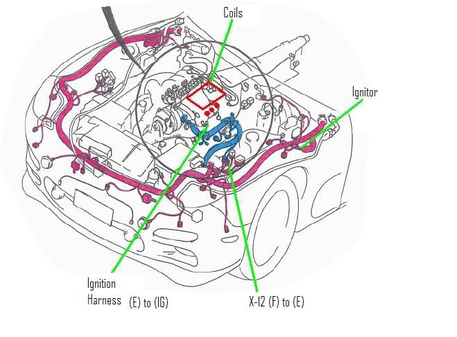 "The Front harness starts at the ECU and wraps around the entire car, inputs the ignitor, then the "shielded" output travels back down the driver's side and connects to the Emissions harness (X-12), travels toward the block where another connector breaks out the IGnition harness." But he was still 100% on track about Mazda's weak system wiring. The stock wiring is longer and has more connectors. This has more resistence than the modded wiring and makes it more vulnerable to EMF/RFI. Since the ignition fires very fast at high rpm's, we need as accurate a signal as possible. Since I'm relocating my coils to under the steering shaft via Garfinkle's bracket, and also placing my HKS twin power down there, now is the best time to do this mod. |
|
|
|
|
|
06-16-2009, 11:05 PM
|
#5 |
|
Rotary Fanatic
Join Date: Mar 2008
Posts: 162
Rep Power: 18 |
The link I posted doesn't go directly to the product. The product I am looking at is 7940K31. The description states, "Has aluminum foil shield bonded to the inside and includes a braided tin-coated copper grounding strap." This product seems very similar to the product ACS describes.
Could I just wrap the wires in aluminum foil, ground it, and headshrink it? LOL jk.  I also came across multiconductor shielded wires (3 wire), but since I need to strip the wires back to solder them, there would be at least an inch of unshielded wiring. Would this be an issue, or is there a way around this? |
|
|
|
|
06-16-2009, 11:41 PM
|
#6 | |
|
Rotorhead
Join Date: May 2008
Location: Drumheller, Alberta
Posts: 164
Rep Power: 18 |
Quote:
__________________
||| Never argue with idiots. They will bring you down to their level and beat you with experience. ||| Last edited by Mobius; 06-16-2009 at 11:47 PM. |
|
|
|
|
|
06-16-2009, 11:58 PM
|
#7 |
|
Rotary Fanatic
Join Date: Mar 2008
Posts: 162
Rep Power: 18 |
You're right, that would be the cleanest. I just ordered a few feet of 3 conductor 18 gauge shielded wiring. If anything, I could also wrap the ends with the shielding also since that's also on the way. I'll post a pic after i finish.
One last question, I'm going to stagger the 3 solder points so that they're not all side by side. Is heat shrink tubing enough insulation for each wire? |
|
|
|
|
06-17-2009, 08:22 AM
|
#8 |
|
Rotorhead
Join Date: May 2008
Location: Drumheller, Alberta
Posts: 164
Rep Power: 18 |
Don't use the dollar store paper thin stuff. Try and find some decent marine or heavier grade heat shrink (preferably the stuff with glue on the inside). IF you can't find anything like that you may want to double wrap the thin stuff.
As long as you don't have any sharp edges poking out of the solder joint, you should be good to go.
__________________
||| Never argue with idiots. They will bring you down to their level and beat you with experience. ||| |
|
|
|
|
06-17-2009, 09:01 AM
|
#9 |
|
Founder/Administrator/Internet Pitbull :)

Join Date: Jan 2008
Posts: 644
Rep Power: 10 |
Please do a write up on this when you do it

__________________
 DGRR 2013 - Year of 13B www.DealsGapRotaryRally.com http://www.facebook.com/Herblenny |
|
|
|
|
06-22-2009, 09:43 PM
|
#10 |
|
Rotary Fanatic
Join Date: Mar 2008
Posts: 162
Rep Power: 18 |
I'm waiting on a lower mileage starter/alternator harness to arrive, and I need the connector from that so I will do a writeup once that arrives and I finish the wiring. This is what I have done so far on the igniter side.
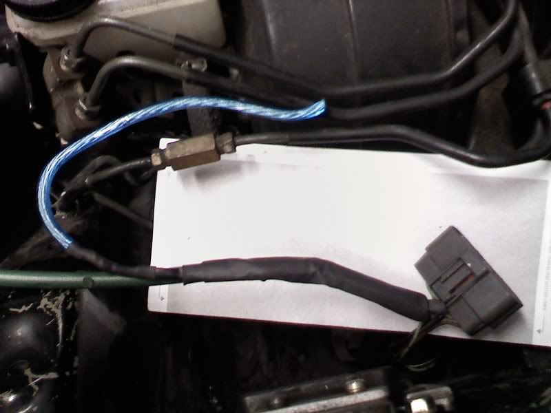 The green wire has 3 wires inside of it soldered to the outputs of the igniter, and is EMF/RFI insulated. The soldered joints have a EMF/RFI wrap around them and the blue wire is the ground for that insulation. Everything is doubled up with very heavy duty heat shrink wrapping to keep any moisture, chemicals, etc. out of the wires. |
|
|
|
|
06-23-2009, 01:19 PM
|
#11 |
|
Viable Fossil

Join Date: Mar 2008
Location: Mid-West
Posts: 199
Rep Power: 18 |
Appologies to the OP because I know this isn't related to his original question but I'm not familiar with the thread on the ignitor to coils re-wire......
Any before and after data?
__________________
Jim VR R1 FD |
|
|
|
|
| Bookmarks |
|
|


 Hybrid Mode
