Quote:
Originally Posted by vex

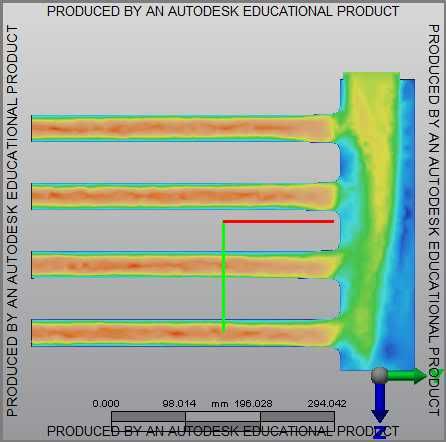
There's been progress on this topic; I just have not been able to get back to it in a very timely manner. As a teaser: Here is a quick and dirty of a prototype intake manifold under CFD testing. I have forgone the use of a diffuser for this run; just to ensure that if I can get a uniform flow at the entrance of the manifold I get a good flow at the runners:
Here's the initial design:

notice the poor flow distribution to the runners. This required me to alter the geometry of the plenum.
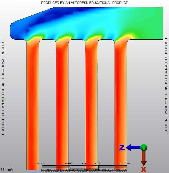
Here's the final prototype:
 |
Good thread and nice work, lots of good info in here. Just a thought though, why haven't you been running your simulations with timed port openings? My brother did some similar work when designing an intake manifold for a V6. He started off modeling airflow with all valves open. The initial simulations yielded what seemed to be horrible airflow distribution:

But before we started making changes to his plenum, we decided it would be best to model the flow in as correct a manner as possible. It took a lot more work to get the time-based model working correctly, but the end results were pretty surprising. The simulation looked to be much more promising, but still not perfect - until we looked at the data from the analysis instead of the visual simulation. All runners received within 0.1% mass air volume!
http://www.youtube.com/watch?v=EpJ4x...ature=youtu.be